Piston Exercise
ME345: Modeling and Simulation Professor Frank Fisher Stevens Institute of Technology Last updated: February 9 th , 2011 Software versions used in the tutorial: SolidWorks 2010. Piston Exercise. Part 1: Intro

Piston Exercise
E N D
Presentation Transcript
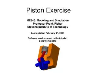
ME345: Modeling and SimulationProfessor Frank FisherStevens Institute of TechnologyLast updated: February 9th, 2011Software versions used in the tutorial:SolidWorks 2010 Piston Exercise
Part 1: Intro In the new SolidWorks Motion, SolidWorks automatically will automatically infer relations between the parts in your assembly based on the mates that you create. In this piston assembly we will be creating mates to control the motion between the crank, arm, piston head, and block to simulate simple motion. First, download and open the assembly corresponding to this tutorial.
Part 2: Setting Up Relevant Mates In this tutorial we will be using simple mates to control the motion of the piston. In this tutorial you can move the parts since, we will have to shuffle them around to mate the proper surfaces. First, lets create some “Concentric Mates”. The first concentric mate will be between the cylinder head and the block. Select the cylindrical face of the block as well as any cylindrical surface on the outside of the head.
Next we want to mate the piston head to the arm. Hit check on the previous mate and select “Concentric” again. As you can see there is no pin present, but the cylindrical mate will suffice.
Hit check on the previous mate and select “Concentric” again. This time we can mate the inner cylindrical face of the arm to the face of the “pin” in the crank. Move the pieces so we can see to see the correct faces to select.
One last concentric mate. Hit check on the previous mate and select “Concentric” again. This time we can mate the outer cylindrical face of the crank to the bottom cylindrical face of the block.
Hit check on the previous mate and select “Coincident”. Now mate the outer face of the arm to inner face of the crank.
Hit check on the previous mate and select “Coincident”. Now mate the end of the crank to the side face of the block.
Part 3: SolidWorks Motion If you have not done so already, hover over the SolidWorks button at the top right, and then go to Tools>>Add-Ins and then check both boxes on the sides of the “SolidWorks Motion”.
Next open up the Motion Study 1 tab at the bottom of the screen.
Add a rotary motor to the crank and change the animation drop down menu to “Motion Analysis”. Hit check.
Run the simulation by hitting play, and then analyze it by clicking the results button.
After clicking “Results” create a graph of the linear displacement of the piston head in the y-direction. Solidworks will prompt you to “Calculate” your results (shown below in the red circle). Once this is done your graph should appear. Create a second graph of the linear velocity of the piston head as well.
We can also edit the type of motion that we give to the rotary motor. Right mouse click on the “RotaryMotor1” feature and select “Edit Feature”. We are going to change it to an oscillating motor. Select the “Constant Speed” drop down, select “Oscillating” and change the input from 90 degrees to 180 degrees.
Hit the check and then “Calculate” to recalculate the results and update your graphs. We are also going to add a result to see the kinetic energy of the piston head. If you want you can switch back to constant speed and see the difference between the two situations.