Download
1 / 13
130 likes | 145 Views
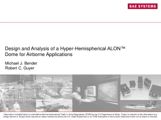
Design and Analysis of a Hyper-Hemispherical ALON™ Dome for Airborne Applications. Michael J. Bender Robert C. Guyer. Introduction. Overview Requirements Installations Environment Stress Analysis Summary. Overview and Requirements. Overview Directable laser IR countermeasure system

E N D
Design and Analysis of a Hyper-Hemispherical ALON™ Dome for Airborne Applications Michael J. Bender Robert C. Guyer
Introduction • Overview • Requirements • Installations • Environment • Stress Analysis • Summary
Overview and Requirements • Overview • Directable laser IR countermeasure system • Multi-axis fine tracking gimbal housed under dome • Requirements • Near IR (2 – 5 micron) transmission • Greater than hemispherical Field of Regard (FOR) coverage • Greater than 6 inch outside diameter • High resistance to sand/dust/rain erosion • High resistance to Foreign Object Damage (FOD) • Producible at an affordable cost
Installations and Environments • Installations • Commercial Aircraft • Tactical Fighter • Environments • Thermal gradients • Altitude-induced pressure gradients • Aircraft maneuver loads • Shock accelerations • Random vibration • High velocity airflow impingement • Foreign Object Damage (FOD) • Electromagnetic Interference (EMI) • Icing
Stress Analysis Approach • Model dome and associated hardware geometry in Pro/ENGINEER CAD software • Import solid model geometry into ANSYS Mechanical 8.1 FEA software • Create 2D Axisymmetric FE model • Analyze static loading (e.g. constant pressure) • Report stresses of worst-case loading • Results from thermal gradient and pressure loads only • Define element type, material properties, mesh, loads, and constraints in ANSYS preprocessor • Solve and plot results in ANSYS postprocessor
FE Modeling – Specifics and Limitations • 2D Axisymmetric model • Major Components • Hyper-hemisphere ALON™ dome • Titanium mounting ring • Adhesive • Linear, static analysis • Reason for 2D • Support many elements in thin cross-sections • High accuracy with reasonable CPU solve time • Limitations • Cannot evaluate dynamic loads • Cannot evalute non-axisymmetric loads • Cannot account for nonlinear or anisotropic material behavior
FE Modeling - Mesh • PLANE82 element (8 node, 2 DOF) • 24,700 elements, 75,745 nodes
FE Modeling – Material Properties, Loads, and BC’s • Material Properties • Loads • Pressure Load • 1 atm (14.7 psi) inside • 1.68 psi (50,000 feet) outside • Thermal gradient • RT to -65°C • Boundary Conditions • Applied on lines Constrain in X only Constrain all DOF’s
FE Modeling - Results • Which computed stresses are appropriate? • Titanium ring • Ductile material with normal and shear loads • Von Mises equivalent stress considered most relevant • Adhesive • Primarily concerned with in-plane shear stress • ALON™ • Von Mises stress not suitable for brittle materials • In spherical regions of dome (away from geometric irregularities), primarily concerned with membrane stresses (meridional and hoop) • Spherical coordinate system, centered at optical center of dome, is used to make stress calculations • Simplifies determination of stress direction (tensile or compressive)
Results • Pressure loading • Thermal loading • Allowable strength of ALON™ based on latest data from Surmet plus additional safety factor of 4 • Design has adequate margin except for adhesive joint • Further adhesive joint design and/or modeling is recommended
Summary • Resultant stresses from thermal loading are worst-case • Highest stress in dome occurs where section is reduced near Ti frame • Except for adhesive under thermal loading, all calculated stresses are below maximum allowable stresses • Strength of ALON™ derived from latest test data from Surmet • Strength of adhesive bonds dependent on the following • Surface preparation • Environment (temperature, humidity, etc.) • Choice of substrate materials • Further analysis and application-specific environmental testing recommended • The impressive mechanical properties of ALON™ make it a viable candidate for high speed aircraft installations