Download
1 / 29
290 likes | 309 Views
This article provides an overview of the upgrades being made to the ATLAS Muon Chambers and Electronics for the Phase 2 of the ATLAS Muon Spectrometer. The upgrades include the installation of new small-strip sTGC trigger chambers and Micromega tracking detectors, as well as the addition of RPC and TGC trigger chambers to improve the muon tracking and trigger capabilities. The article also discusses the development of thin-gap RPCs and their front-end electronics for operation at the HL-LHC.

E N D
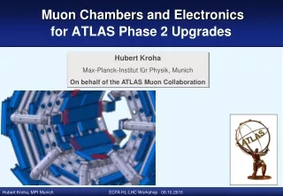
Hubert Kroha Max-Planck-Institut für Physik, Munich On behalf of the ATLAS Muon Collaboration Muon Chambers and Electronics for ATLAS Phase 2 Upgrades
ATLAS Muon Spectrometer BO BM BI EI EM EO About 1200 Monitored Drift Tube (MDT) precision tracking chambers with in total 140k drift tubes: sense wire positioning accuracy of 20 μm and chamber spatial resolution of 40 μm. Track sagitta measurement in 3 detector layers. Optical alignment system with 30 μm sagitta correction accuracy. Combined with 600 RPC (double gas gaps, barrel BM, BO) and 3600 TGC (endcaps) trigger chambers for L1 muon trigger, BCID and 2nd coord.measurement (< 10 ns time and order cm spatial resolution). High neutron and gamma background rates: up to 400 Hz/cm2 in EI MDTs at LHC design luminosity. About 7 x higher background rates expected at HL-LHC, as well as much increased muon trigger rate.
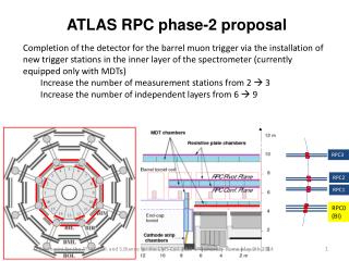
Muon System Upgrade Strategy for HL-LHC Strengthening of the endcap muon tracking and trigger by installing new Small Wheels in the EI layer with high-resolution small-strip sTGC trigger chambers and Micromega tracking detectors with much increased rate capability already in LS2 (2019-20). Extension of the EI sTGC trigger chamber layer to larger radii in LS3 (2024-26) under consideration. Overview of ATLAS muon system upgrades in one quadrant
Muon System Upgrade Strategy for HL-LHC 2 Strengthening of the barrel muon trigger by installing 276 additional RPC chambers in the BI layer - to close acceptance gaps and redundancy, in particular - to compensate for potential efficiency loss of the existing . . RPCs when operated beyond their anticipated lifetime. Requires also replacementof the 96 BIS MDTs by small-diameter sMDT drift tube chambers . to make space for the new RPCs and increase the tracking rate capability (10 x). Pilot project for Phase 1 upgrade: 16 new sMDTs with RPCs at the ends of the BIS layer (BIS7/8). 4
Muon System Upgrade Strategy for HL-LHC 3 Improvement of the 1st level muon trigger selectivity(see previous talk) by including the (s)MDT chambers in the trigger to achieve at trigger level the highest possible . muon momentum resolution and selectivity. - Requires implementation of fast readout of the drift tubes, . i.e. replacement of the MDT on-chamber electronics, esp. new TDC and data concentrator (CSM). - New MDT front-end and RPC trigger electronics also required to cope with . the increased rate(≥ 1 MHz) and longer latency ( 6 -10 μs) of the new 1st level trigger at HL-LHC. 5
Thin-gap RPCs for HL-LHC • Present RPCs are certified up to rates of 100 Hz/cm2 over 10 years of LHC operation w/o efficiency loss. • Both counting rates and total operation time will be exceeded at HL-LHC. • Reduce HV and accumulated charge (but also efficiency). • Reduction of HV may also be necessary for the use of new eco gases (ongoing ATLAS/CMS efforts). • Backup with new BI RPCs. Backround rates of up to 600 Hz/cm2 expected in the new RPCs in BI layer at HL-LHC. • Development of new thin-gap RPCs . with 1/2 gas gap and 2/3 electrode thickness and new highly sensitive amplifiers . which can be operated at much lower voltage and, therefore, much lower charge/hit . such that their lifetime under irradiation becomes substantially longer. Triplet of gas gaps, required minimum, maximum fitting into the BI layer (only 50 mm thickness). Challenging mechanics and elx. shielding. Light-weight support structure and electronics shielding FEE boards Readout panels with half the present thickness (, strips on the top/bottom panels/gap).
Thin-Gap RPC Design Criteria • Smaller gas gap (1 mm instead of 2 mm) between two bakelite electrodes • - helps to reduce chamber thickness, • - gives twice better time resolution (0.4 ns instead of 1 ns) and less charge fluctuations, • - operatew with same gas gain and efficiency at substantially lower voltage (6 kV instead of 9.6 kV). • Thinner bakelite electrodes (1.2 mm instead of 1.8 mm) • - allow for further reduction of chamber thickness and weight, • - increase the signal charge induced on the strips. • Together with new low-noise charge amplifiers • - allows for further lowering of the operating voltage to 5.4 kV, • corresponding to 15 x lower gas gain and avalanche charge without efficiency loss; • also provides more room for new eco gas choice. • More than sufficient for operation at 6 x higher rates than present limit over 10 years at HL-LHC • (safety factor of 2.5). 7
Thin-Gap RPC Front-End Electronics Development New fast low-noise charge amplifier for much smaller signals at the reduced gas gain
Thin-Gap RPC BI Triplet Mechanical Design Very challenging space constraints: only 50 mm available.
BIS7/8 RPC Prototype Construction Optimisation of strip panel layout and electrical shielding.
BIS7/8 RPC Prototype Test Test of single gas gaps in muon beam and under irradiation in GIF++ at CERN in May 2016 without irradiation 600 kHz/cm2 Increasing rate
Small Diameter Drift Tube (sMDT) Chambers By reducing the tube diameterfrom 30 mm (MDT) to 15 mm (sMDT) at otherwise the unchanged operating conditions (Ar:CO2 (93:7) at 3 bar, gas gain 20k, i.e. voltage 3070 V): 8 x lower background occupancy (4 x shorter maximum drift time, 2 x smaller tube cross section). reduce electronics deadtime (≈ max. drift time)by a factor of 4, thus the masking of muon hits by preceeding background hits. 10 x higher rate capability of sMDTs compared to MDTs. MDT sMDT 30 mm 15 mm Drift time spectrum 50% occupancy 6.5% occupancy Also: twice as many tube layers fit into the same available detector volume. 185 ns 700 ns
Space Charge Effects • Why 15 mm tube diameter? • Space charge effects due to background radiation are strongly reduced in sMDT tubes: • Effect of space charge fluctuations eliminated for r < 7.5 mm due to almost linear r-t relation. Gain loss suppressed proportional to r3 and less primary ionization. MDT Space-to-drift time relation in Ar:CO2 (93:7), 3 bar sMDT 185 ns MDT 700 ns Measurements performed at the CERN Gamma Irradiation Facility Max. rates in MDTsat HL-LHC
Rate Capability of sMDT Drift Tubes Measurements at GIF with standard MDT readout electronics (bipolar shaping) and minimum adjustable deadtime of 220 ns for sMDTs (820 ns standard deadtime for MDTs). Average spatial resolution Muon efficiency MDT sMDT with BLR sMDT sMDT with BLR sMDT MDT BI EM max. background flux in MDTs at HL-LHC max. background hit rates at HL-LHC sMDT rate capability limited by current readout electronics due to signal pile-up effects (signal loss and additional time slewing). Can be suppressed using baseline restoration (BLR) like in ATLAS TRT, not needed for muon system at HL-LHC. 185 ns bipolar shaping 700 ns
sMDT Chamber Design Design and assembly procedures optimized for mass production. Simple, low-cost drift tube design ensuring high reliability. Industry-standard aluminum tubes (0.4 mm wall thickness). Sense wire position defined by metal insert alone with high accuracy. Injection molded endplug and modular gas connector materials selected to prevent outgassing and cracking. No aging observed up to 9 C/cm charge accumulated on the wire (MDT requirement: 0.6 C/cm). internal wire locator external reference surface
Automated Drift Tube Assembly Wire insertion by air flow Wire tension measurement Wire tensioning: 350 g ± 4% Temperature controlled clean room. Assembly of 100 tubes/day per station. Failure rate below 1%. Endplug and wire fixation
sMDT Chamber Construction Design for mass production of chambers large numbers of tube layers: Assembly withinone working day independent of the number of layers. Endplug insertion in jigging holes Stacking of tube layers Completed BMG chambers Gas distribution system
New sMDT and RPC Chambers for ATLAS RPC sMDT Construction 2015/16, completed. Installation in the detector feet in EYETS 2016/17 sMDT + triple thin-gap RPC for ends of the BIS layer Installation in LS2. Pilot project for replacement of BIS layer in Phase 2
Quality Control: Mechanical Wire Position Measurement Measurement of individual sense wire and alignment sensor positions with with 3D coordinate measuring machine. Wire positions known with 2 μm precision. Wire positioning accuracy of better than 5 μm, at the limit of the jigging precision, most precise chambers of such size (MDTs: 20 μm). Internal wire locator External reference surface
Integrated BIS Chamber Design Highly integrated design of sMDT + RPC chambers for Phase 1 upgrade, well advanced Model for Phase 2 BIS layer design. Very challenging space constraints. RPC triplet, with 50 mm thickness BIS 7 BIS 8 In-plane and global alignment
(s)MDT Readout Electronics Development for Phase 2 • New ASD and TDC chips in 130 nm IBM CMOS technology supported by CERN (now Global Foundaries) with sufficient radiation hardness are already under development, • both for replacement of MDT front-end boards and for the new sMDT chambers at HL-LHC. • Latest submissions in August 2016. Expected to be final ASD iteration. Prototype ASD II chips, 6.6 mm2 size Alternatively, also FPGA implementation of the new fast-readout TDC under investigation.
(s)MDT Readout Electronics Development for Phase 2 Performance requirements for the ASDs are unchanged compared to Phase 1, but present chips in 500 nm Agilent CMOS technology cannot be fabricated anymore. • Same architecture as the present ASD chip: • bipolar shaping, peaking time 15 ns, Wilkinson ADC for time-slewing corrections: 100 μm 80 μm • MDT drift tube resolution. • New TDCs will enable fast readout of drift time information for the (s)MDT-based 1stlevel muon trigger • with order 1 ns resolution at up to 5 Gbps data rate at HL-LHC. • Design of a new data concentrator (Chamber Service Module, CSM) also started. 22
sMDT Readout Electronics High-voltage distribution boards (24 channels) Signal distribution and readout boards (24 channels) with three 8-channel amplifier-shaper-discriminator (ASD) chips and one TDC chip (here: CERN HPTDC for Phase 1 upgrades) Coupling capacitor in barrel Challenge of 4 x denser tube grid: Direct connection to endplug signal pins. HV protection of termination resistors and coupling capacitors. Stacked passive and active boards.
Conclusions ATLAS muon spectrometer Phase 2 upgrades are defined (IDR October 2016, followed by TDR mid 2017). R&D for new muon chambers (barrel: thin-gap RPCs, sMDTs; endcap: sTGCs) and for (s)MDT front-end electronics replacement with fast readout for new MDT-based 1st level muon trigger is quite advanced. The new RPC development is also persued as an AIDA 2020 project. Well understood detector technologies have been further improved to cope with higher rates and space constraints. They also fit well into the existing framework of services, alignment, DAQ and software. Pilot projects and detailed designs are already on the way for Phase 1 upgrades.
Muon System Upgrade Strategy for HL-LHC Improvement of the 1st level muon trigger selectivity by including the MDT chambers in the trigger to achive the highest momentum resolution. Requires implementationof fast readout of the MDT chambers, i.e. replacement of the MDT on-chamber electronics, in particular new TDC and data concentrator (CSM). New MDT front-end and RPC trigger electronics is also required to cope with the increased rate (≥ 1 MHz) and longer latency of the 1st level trigger at HL-LHC.
ATLAS Barrel Muon Chamber Upgrades Q1 2017: BMG12 sMDT chambers to improve the momentum resolution (by factor of 2 at 1 TeV) in the detector feet. 2019-20 (LS2):BIS 7/816 sMDT + 32 RPC chambers to improve the trigger selectivity and the rate capability in the barrel inner layer. Pilot project for phase 2 upgrade. New Small Wheels to increase rate capability of tracking and trigger detectors and trigger pT resolution together with MDT-based trigger. 2024-26 (LS3): BIS, BIL 1-6 96 sMDT + 276 RPC chambers for the barrel inner layer to increase the robustness of the barrel muon trigger system. Use of (s)MDT chambers for the 1st level muon trigger to increase pT resol. and selectivity. New MDT on-chamber electronics because of 10 x higher trigger rate and MDT-based trigger. 2014 (LS1):BME 2 sMDT + RPC chambers to improve acceptance and momentum resolution in the bottom barrel sector. In operation since Run 2.
Background Rates in RPCs at HL-LHC Present RPCs are certified up to rates of 100 Hz/cm2 over 10 years of LHC operation w/o efficiency loss. Both rates and total operation time will be exceeded at HL-LHC. maximum in present BM layer RPCs Hz/cm2 • Reduce HV andaccumulatedcharge (but also efficiency). Backup withnew BI RPCs. Backroundratesupto 600 Hz/cm2 areexpected in thenew RPCs in BI layer at HL-LHC! 27