Download
1 / 24
270 likes | 358 Views
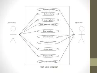
A detailed guide on creating a use case diagram for a University Record System, including main functions, actors, and relationships in the system.

E N D
Use Case Diagram • A use case diagram is a type of behavioral diagram, used for describing a set of user scenarios • Mainly used for capturing user requirements • Work like a contract between end user and software developers. • The main purpose of a use case diagram is to show what system functions are performed for which actor. • The diagram present a graphical overview of the functionality provided by a system in terms of actors, their goals (represented as use cases), and any dependencies between those use cases and actors.
Notations in Use Case Diagram 1-Use Case : Each use case on the diagram represents a single task that the system needs to carry out. • For example (Buy a Product, Add Client …) One use case
Notations in Use Case Diagram (Cont.) 2-Actor : An actor is anything outside the system that interacts with the system to complete a task. • It could be a user or another system. • actor "uses" the use case to complete a task.
Notations in Use Case Diagram (Cont.) 3-System Boundary: It is usual to display use cases as being inside the system and actors as being outside the system.
Scenarios in Use Case • A scenario is a formal description of the flow of events that occur during the execution of a use case instance. • It defines the specific sequence of events between the system and the external actors.
Relationships in Use Case Diagram • Relationship between actors: • Generalization/Specialization. • Relationships between use cases: • Include. • Extend. • Generalization/Specialization. • Relationship between actors and use cases: • Association.
Relationship between Actors Generalization/Specialization : Generalization is a relationship between two actors. Where A is a generalization of B, it means A describes more general behavior and B a more specific version of that behavior.
Relationships between Use Cases 1-Include: Use the includes link to show that one use case includes the task described by another use case. Example:
Relationships between Use Cases (Cont.) 2-Extend: Use the Extends link to show that one use case extends the functionality of another use case at specific Extension Points. Example:
Relationships between Use Cases (Cont.) Extend Example :
Relationships between Use Cases (Cont.) 3-Generilization: The generalization link is an informal way of showing that one use case is similar to another use case, but with a little bit of extra functionality. One use case inherits the functionality represented by another use case and adds some additional behavior to it.
Relationships between Actors and Use Cases Association: The association is the link that is drawn between actor and a use case. It indicates which actors interact with the system to complete the various tasks.
Include relationship : a standard case linked to a mandatory use case. • Standard use case can NOT execute without the include case tight coupling . • Extend relationship : linking an optional use case to a standard use case. • Standard use case can execute without the extend case loose coupling.
How to Create Use Case Diagram 1. List main system functions (use cases) in a column: • Users’ goals/needs to be accomplished via the system • Create, Read, Update, Delete (CRUD) data tasks 2. Draw ovals around the function labels 3. Draw system boundary 4. Draw actors and connect them with use cases (if more intuitive, this can be done as step 2) 5. Specify include and extend relationships between use cases
UniversityRecordSystem(URS) A University record system should keep information about its students and academic staff. Records for all university members are to include their id number, surname, given name, email, address, date of birth, and telephone number. The system should be able to handle the following commands. Add and remove university members (students, and academic staff) Add and Delete subjects Assign and Un-assign subjects to students Assign and Un-assign subjects to academic staff.
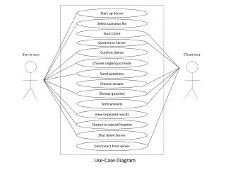
URS Del member System User Academic Add subject Del subject Assign subject Un assign subject enrolll subject Student Un enrolll subject UniversityRecordSystem(URS) Add member
8. The system checks that the user is not already enrollled on a course whose timetable clashes with the chosen course. [Alt 4: User is not eligible to enroll due to timetable clashes] 9. The system records that the user is now enrollled to the chosen course, updating the list of students. 10. The system informs the user that enrollment has been successful, and offers the student the opportunity to receive proof of enrollment. 11. The user elects to obtain proof of enrollment. [Alt 5: User declines proof of enrollment] 12. The system provides the user with proof of enrollment. 13. The system provides the user with the opportunity to enroll for further courses [Alt 6: User elects to enroll for further courses] or to exit the use case [Use Case
Conclusions • Use cases are powerful tools for analysts to use when partitioning the functionality of a system. • Use case relationships and the corresponding diagrams help analysts to structure use cases such that their textual descriptions contain a minimum of redundant information, thus making the whole text document much easier to maintain. But use cases are not design tools. • They do not specify the structure of the eventual software, nor do they imply the existence of any classes or objects. • They are purely functional descriptions written in a formalism that is completely separate from software design.