Download
1 / 12
170 likes | 577 Views
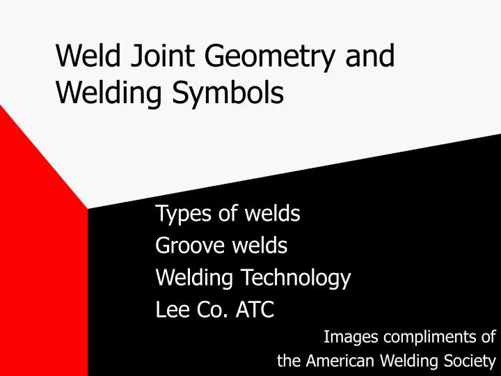
Weld Joint Geometry and Welding Symbols. Types of welds Groove welds Welding Technology Lee Co. ATC Images compliments of the American Welding Society. Types of Welds. Numerous welds can be applied to the various types of joints

E N D
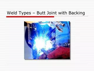
Weld Joint Geometry and Welding Symbols Types of welds Groove welds Welding Technology Lee Co. ATC Images compliments of the American Welding Society
Types of Welds • Numerous welds can be applied to the various types of joints • Considerations when choosing joint geometry and weld types: • accessibility to the joint for welding • type of welding process being used • suitability to the structural design • cost of welding
Types of Welds • There are nine categories of welds associated with weld symbols • Groove welds • Fillet Welds • Plug or Slot welds • Stud welds • Spot or projection welds • Seam welds • Back Or Backing welds • Surfacing welds • Flange Welds
Types of WeldsGroove Welds • A groove weld is “ a weld made in a groove between the work pieces” • There are eight types of groove welds • Square-groove • Scarf • V-groove • Bevel-groove • U-groove • J-groove • Flare-v-groove • Flare-bevel-groove
Groove Welds Square and double square-groove welds • Square-groove welds are the most economical to use, but are limited by thickness of the members • Welds for one side are normally limited to a 1/4 inch or less
Groove WeldsV-and double V-groove welds • With thicker materials joint accessibility must be provided for welding to ensure weld soundness and strength
Groove WeldsBevel- and double-bevel-groove welds • Bevel- and J- groove welds are more difficult to weld than V- or U- groove welds • Bevel welds are easier in horizontal
Types of Welds U-groove and Double U-groove • Welds in using J- and U-grooves can be used to minimize weld metal • These welds are very useful in thicker sections
Groove WeldsJ-and double-J-groove welds • J-groove are more difficult to weld because of the one vertical side (except in horizontal) • J-and U- are used when economic factors outweigh the cost of edge preparation
Groove Weldsflare-bevel and flare-v-groove welds • Flare -bevel and flare-v-groove welds are used in connection with flanged or rounded member
Groove WeldsScarf • Scarf is used for brazing
Groove Welds • Their names imply what the actual configurations look like when viewed in a cross section • Single groove welds are welded from only one side • Double groove welds are welded on both sides • Groove welds in many combinations are used selection is influenced by accessibility, economy, adaptation to structural design