Download
1 / 14
140 likes | 572 Views
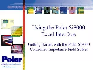
Using the Polar Si8000 Excel Interface. Getting started with the Polar Si8000 Controlled Impedance Field Solver. The Polar Si8000 Field Solver. The Polar Instruments Si8000 Field Solver uses the familiar Microsoft Excel for Windows interface for easy graphing and data sharing.

E N D
Using the Polar Si8000 Excel Interface Getting started with the Polar Si8000 Controlled Impedance Field Solver
The Polar Si8000 Field Solver The Polar Instruments Si8000 Field Solver uses the familiar Microsoft Excel for Windows interface for easy graphing and data sharing. Using Excel’s powerful Autofill and Chart Wizard features, the Si8000 can rapidly chart Z0 against a varying parameter, providing easy comparison and evaluation of the behaviour of most popular controlled impedance structures. The tutorial assumes you have a basic working knowledge of Microsoft Excel. The Si8000 formulas included in Microsoft Excel format enable advanced functions,for example, sensitivity analysis and graphing the effects of a range of parameter value changes.
Graphing impedance, Z0 vs dielectric height, H1 In this tutorial we use Excel to graph impedance, Z0, vs dielectric height, H1, in a single dielectric surface microstrip structure and predict impedance change due to variations in laminate thickness. Knowing how Z0 varies with H can help you increase yields by making process adjustments to compensate for base material variation.
How to use this tutorial The Field Solver functions for each controlled impedance structure are built into the Excel workbooks Si8000.xls and Si8000Expert.xls. Please run through all the slides in this presentation to give yourself an overview. Then launch the Si8000 and click the Surface Microstrip graphic and work through the examples. The Si8000.xls workbook includes pre-built sample data worksheets incorporating tables of functions and their associated parameters. If you are not familiar with some of the features of Excel, you may find it worth taking a brief course to get the best from your Si8000.
Choosing the Si8000 structure In this introductory tutorial we view the Si8000’s structure page and choose the Surface Microstrip controlled impedance structure Launch the Si8000and click the Surface Microstrip graphic
Si8000 Surface Microstrip structure Each Si8000 structure page includes a table containing the structure function along with its associated parameters (shown supplied with predefined values) and an embedded chart that uses the table as its data source
Si8000 Surface Microstrip structure The chart defaults to graphing Z0, impedance against H1, the substrate height. You can use the Excel Chart Wizard to change the chart source data to show results for other columns. We use Excel’s Fill Handle to copy the formula to the cells below
Si8000 Surface Microstrip structure Excel’s Fill Handle (the black + sign at the lower right corner of the active cell) provides a convenient way to copy data or formulas to adjacent cells. Drag and copy the formula down to the target height
Si8000 Surface Microstrip structure We use the Excel Chart Wizard to change the chart source data to reflect the new range of H1 values. Now click Calculate Change the X axis to display the range of Height values
Si8000 Surface Microstrip structure The Si8000 calculation engine displays its progress during field solving. Now click Calculate… …and watch this space…
Si8000 Surface Microstrip structure The Si8000 fills in the correct values in the table. Now from the chart we can see how Z0 changes with core dimensions. We can easily change other parameters in the table, recalculate and chart the effects.
Si8000 Surface Microstrip structure To calculate other characteristics for the selected parameters, enter the value D, L, C, etc., in the associated cell in the Calc Type column (labelled Calc Type), move to another cell and press the Calculate button. Re-label the results column if necessary. Move the mouse over the Calc Type label to see which characteristics are available for a structure.
Thank you for using this presentation This presentation is just one of a series of hands-on tutorials designed to help you get the most out of your Si8000 Field solver Please view our other step-by-step presentations available on the Polar Instruments web sitewww.polarinstruments.com
For more information contact Polar now: Phone: USA / Canada / MexicoKen Taylor( 503) 356 5270 Asia / Pacific Calvin Sie +65 6873 7470 Japan Terumitsu Tsuji +81 45 339 0155UK / EuropeNeil Chamberlain +44 23 9226 9113 Germany / Austria / Switzerland Hermann Reischer +43 7666 20041-0 www.polarinstruments.com