ISE 167 Laboratory
1.11k likes | 1.45k Views
ISE 167 Laboratory. Welcome to the lab Green Sheet Schedule Adds, drops, etc. ProModel ™ is loaded in E405, E407 on first come, first served basis. ISE 167 Laboratory. Lab Tour ProModel Tour Sequence of Solution

ISE 167 Laboratory
E N D
Presentation Transcript
ISE 167 Laboratory • Welcome to the lab • Green Sheet • Schedule • Adds, drops, etc. • ProModel™ is loaded in E405, E407 on first come, first served basis
ISE 167 Laboratory • Lab Tour • ProModel Tour • Sequence of Solution • Prologue program: Keep this on disk, as we will be modifying it (as needed) to illustrate the lab concepts.
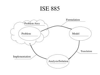
ProModel™ - Sequence • Essentially, this is no different than a top-down computer programming exercise. • First, define what you have, and what you need. • Haves: Entities, arrival schemes, locations, processing limits (if any). • Needs: Process details, system statistics, entity statistics
ProModel™ - Sequence • It is usually easier if you draw a picture / flow chart / etc. Note: This will be required for your reports. • It is also usually easier to work backwards from the “needs” to the “haves” as one would do in chemical synthesis.
ProModel™ - Sequence • Once a clear picture of what is required is defined, then declare and define the following modules within ProModel: • Locations • Entities • Arrivals • Processing • Variables • Fun Stuff
ProModel™ - Locations • Locations are where events are carried out upon entities flowing through the system. • On some versions, limited numbers of locations are available. There may be occasions where creativity will be needed to model the system (but not for a while…).
ProModel™ - Locations • Things to define in the Location module found under the “Build” tab: • Name • Capacity – How many entities at a time • Units – How many of this location type • DTs – Downtime logic (covered later) • Rules – Decision rules (FIFO, random, etc.) • Color, size, and layout placement can be done.
ProModel™ - Entities • These are defined (within ProModel!) as the parts that flow through the system. • The entities are often also limited in number, depending upon the program type, so creativity may again be required. • Entities are discrete units that can be bundled. This aspect is covered later.
ProModel™ - Entities • Things to define in the “Entities” module under the “Build” tab: • Name • Speed of Travel (default is 150 fpm) • Color, size, etc. • Attributes are set by a separate module under “Build” and cover locations and entities. This is a future topic as well.
ProModel™ - Arrivals • Arrivals are defined for entities entering the system. • Can be a single occurrence, infinite, or anything in between, as defined in the logic. • Each entity entering the system will have its own arrival protocol.
ProModel™ - Arrivals • Things to define for “Arrivals” under the “Build” tab: • Entity Name • Location of arrival • Quantity at each arrival • First time of arrival (default is when the system FEL causes the arrival)
ProModel™ - Arrivals • Things to define for “Arrivals” under the “Build” tab, continued: • Occurrences – number of times arrivals will occur during the simulation • Frequency – Logic for when arrivals occur, can be either an integer number or a distribution that has all required parameters (Note that Uniform Distribution uses the half width as a parameter) • Logic – Special conditions, etc.
ProModel™ - Processing • This is where the meat of the program is defined. Following the road map (picture) that was developed, walk each entity through all of the processing steps from start to finish. During this time, name and locate the variables used to track the performance of the model / system. • One other caveat: the system will do exactly what it is told to do, so when cutting and pasting, be sure you don’t change the entity name in processing.
ProModel™ - Processing • Things to define for “Processing” under the “Build” tab: • Incoming Entity (one entry allowed) • Location – where the entity is NOW • Operation – What logical steps are to be applied to the entity at the location above. Can be waits, updates on tracking variables, costing, etc. • Output – Declare the SAME entity unless you are really intending to change entities in this step.
ProModel™ - Processing • Things to define for “Processing” under the “Build” tab, continued: • Destination – The target location. Can be more than one, but each location is defined separately, using the return key. If more than one location is used as a target, you need rules for selection. • Rule – This section defines the logic for how and which location gets the entity, whether as a preloaded subroutine or a user-defined subroutine. • Move Logic – Used for Resources, primarily.
ProModel™ - Variables • Variables are used for tracking system, location and entity performance. • Can be used for verification purposes. • Essentially there is no limit on the number of variables that can be issued.
ProModel™ - Variables • Things to define for “Variables” under the “Build” tab: • ID – Declares the variable name • Type – Integer or real, default is integer • Initial Value • Notes – Useful for large programs to track what this variable is supposed to do. • Icon – This tells you when a counter appears on the layout.
ProModel™ - Fun Stuff • More items available, and to be discussed later: • Resources – Forklifts, techs and the like. • Path Networks – used to constrain movements within a shop model, for example. • Arrays, Macros, User Distributions, etc. help convert the process into a definable model. • Background Graphics can be used for labeling and identifying components in a layout.
ProModel™ - Distributions • Distributions are declared in ProModel shorthand, thusly: • N(12,3) means a normal distribution with mean 12 and standard deviation of 3. • U(10,1) means a uniform distribution with a center of 10 and a half-width of 1 (ranges from 9 to 11). • T(1,2,3) means a triangular distribution with a minimum of 1, a mode of 2, and a maximum of 3. • E(5) means an exponential distribution with a mean time between events of 5.
ProModel™ - Distributions • All distribution types have theoretical expected values and variances, refer to the ISE 130 notes, or your text for these. • The expected values are to be used for model verification in comparison to the model-generated confidence intervals.
ProModel™ - Attributes • Two types: Entity and Location. Entity is more common. • Attributes can be examined and acted upon by the logic in any part of the program from arrivals to departures. • Attributes of an entity are copied over whenever an entity is cloned. This happens when entities are split, for example.
ProModel™ - Attributes • Within ProModel, select the Attribute field from the drop-down Build menu. • The required elements are “name”, “type” (integer / real), and classification. • Values are assigned in the logic. • Attributes are especially useful when assigning a user condition for routing.
ProModel™ - Attributes • Today’s exercise for the prologue is to do the following: • Create an attribute for the entity to bypass the inspection step as a “good part” since it comes from an ultra-reliable supplier. One third of the entities received are from this supplier. Track the bypassed as well as the good parts in the graphics.
ProModel™ - Downtimes • These are elements used to model situations where a part of the simulation is not available for operations. • The setup field is available for Locations and Resources, primarily. • Types of downtimes include intentional (e.g. maintenance or breaks) and casualty.
ProModel™ - Downtimes • For locations, select the Build -> Locations sequence. • For a given location, go to the DTs field and select the task button. • There are four types of downtime: clock, entry, usage, and setup.
ProModel™ - Downtimes • Types of Downtimes: • Clock – models downtimes on a time basis, regardless of entity usage. Downtime begins if no entity is being processed. • Entry – models downtimes on an entry usage basis, after the triggering entity has left the location.
ProModel™ - Downtimes • Types of Downtimes: • Usage – models downtimes on a time basis, regardless of entity usage. Blocked time is not included which differs from clock. Also, usage is only available for single-capacity locations. • Setup – models downtimes on an entry change basis, when the triggering entity has arrived at the location. Available only for single-cap locations, it models the setup time to swap tooling.
ProModel™ - Downtimes • Clock Fields • Frequency: Time between successive downtimes, can be scalar or expression. • First time: Determined by frequency logic if left blank. • Priority: Code assigned if downtime is preemptive, default is “99” if not assigned.
ProModel™ - Downtimes • Clock Fields • Scheduled: Determines whether the downtime is scheduled. If yes, the hours spent in downtime are not considered when determining utilization, percent down, etc. • Logic: Where the delay is defined, either as a “wait” statement or something more complex that utilizes an attribute, etc.
ProModel™ - Downtimes • Entry Fields • Frequency: Number of entities between successive downtimes, can be scalar or expression. • First time: Determined by frequency logic if left blank. • Logic: Delay action defined as for clock.
ProModel™ - Downtimes • Usage Fields • Frequency: Usage time (not blocked) between successive downtimes, can be scalar or expression. • First time: Determined by frequency logic if left blank. • Priority: As defined for clock. • Logic: Delay action defined as for clock.
ProModel™ - Downtimes • Setup Fields • Entity: The incoming entity. The reserved word “ALL” can be used for identical setups, but logic will be needed to model the delay properly. • Prior Entity: The previous entity. “ALL” can be used here as well. • Logic: Delay action defined as for clock.
ProModel™ - Downtimes • Today’s exercise for the prologue is to do the following: • Create a downtime field for the machining and inspection activities. When they go down, the waiting time for recovery is defined as follows: • Inspection: U(15,2) with frequency of 150 min, unscheduled • Machining: T(12,15,20) with frequency of 10 hours, scheduled, and N(20,3) with frequency of E(100) parts
ProModel™ - Downtimes • Today’s exercise for the prologue, continued: • Compare the input queue length, utilization, and throughput (e.g. the total good parts) for the one machine and two inspector case. As always, remember to use 95% C.I.s.
ProModel™ - Resources • A Resource is person, equipment item, or device that performs the following functions: • Entity transport • Assisting in operations (such as an inspection) • Location maintenance • Resource maintenance
ProModel™ - Resources • Resources can consist of one or more units with common characteristics, such as a group of forklifts. • Resources can be dynamic (requiring a path network) or static. Downtimes are also included as part of the model. • Resources have names and name-index numbers. Path networks also have names and nodes.
ProModel™ - Resources • Access the Resource fields by Build -> Resources. The following fields are available: • Icon – The ProModel icon attached to the resource name • Name • Units – Fixed at the beginning of the simulation run, so downtimes should be used to vary the number of a given resource available.
ProModel™ - Resources • Stats • Specs – Defines the network used (if any), set the speed, and define pickup / delivery times. • Search – Sets the Work Search and Park Search logic when path networks are used. • Logic – Refers to the operational logic executed when the resource enters or leaves at a particular path node. • Pts – Auxiliary graphical storage locations.
ProModel™ - Resources • Static Resources • Will appear in only one location during the operation of the model, however, it can be used logically to move entities between locations. • There is no status light, but the resource will be green when in use and red when down (if no other graphics are used).
ProModel™ - Resources • Dynamic Resources • Requires definition of the Path Network before creation, since it will be referenced in the Specifications dialog box. • The Specifications dialog box defines the rules by which the resource will operate. • Each Resource is defined using the Build -> Resources task sequence
ProModel™ - Resources • Fields for Building Resources • Name – The user-defined name of the resource • Units – The program will give it a suffix similar to the location • DTs – As for Locations, Clock and Usage only. Individual units can be selected. • Stats – As for Locations
ProModel™ - Resources • Fields for Building Resources, continued • Specs – Provides exact details for Resource implementation. • Search – Separate from the one in Specifications, this refers to the work search (where the jobs are) or the park search (where idle time is allowed) • Logic – Logic defined for when networks are accessed or left • Pts – Used for graphical location of icons
ProModel™ - Resources • Details on New Things • Specs – Subunits include the defined path network (not assigned if static), the node specifications, the search logic for resources and entities, and motion rules. • Node specifications – the “home” node is where the resource begins the simulation. Check the “Return Home” if the resource is to return to the home node if idle. Otherwise, it waits where it is.
ProModel™ - Resources • Specs, continued • Resource and Entity Search – These define the rules for selecting the next resource and entity to be used. • Motion – These define the speeds and handling times for entities processed by the resource.
ProModel™ - Resources • Dynamic Resources • Resource Searches: • Work Search – A list of locations where entities are waiting for pickup. Can be exclusive (can only service its list), or non-exclusive (will default to the Resource Search rule if no work is available in its list) • Park Search – A list of nodes where the resource will park if no work is available
ProModel™ - Path Networks • Select from Build -> Path Networks • Name – The network name • Type - Passing or non-passing, where the network segment has to be clear to run a resource along it • T/S – Selects the basis for measuring movement along the node, either as Time or Speed and Distance
ProModel™ - Path Networks • Paths – The number of path segments in the network. Clicking on the heading button opens the edit table • Interfaces - The number of location-node interfaces in the network (entity dropoff / pickup points) • Mapping – Used to specify nodes for restricting movements • Nodes – The number of nodes in the network, controlled using the Node Edit table
ProModel™ - Path Networks • Path Segment Editing • From and To - The beginning and ending segment nodes. • BI – Used to specify whether uni- or bi-directional travel is allowed on the segment. • Distance (or Time) – The specified distance between the nodes. Default is based on the network graphic layout
ProModel™ - Path Networks • Interface Editing • Node - The node number • Location – Used to specify what location is attached to a node number. Locations can be only interfaced with one node, but a node can be interfaced with multiple locations • Mapping Editing – Multiple-branch networks will select paths with the minimum path length. Mapping forces a specified path for a given node destination.
ProModel™ - Path Networks • Node Editing • Node - The node number • Limit – The maximum number of resources that can occupy a given node. Blank means unlimited. • Path networks are assigned to resources using the resource dialog box described earlier