Download
1 / 15
150 likes | 328 Views
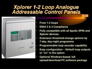
Xplorer 1-2 Loop Analogue Addressable Control Panels. From 1-2 loops EN54 2 & 4 Compliance Fully compatible with all Apollo XP95 and Xplorer devices Extensive threshold-change options by 7-day, day-night programme Programmable loop sounder capability

E N D
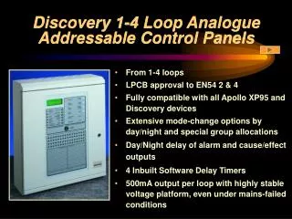
Xplorer 1-2 Loop Analogue Addressable Control Panels • From 1-2 loops • EN54 2 & 4 Compliance • Fully compatible with all Apollo XP95 and Xplorer devices • Extensive threshold-change options by 7-day, day-night programme • Programmable loop sounder capability • Easy configuration – Default loop outputs to “on” in fire option • Optional Windows-based, full upload/download PC software package
Xplorer 1-2 Loop Analogue Addressable Control Panels • 500mA output per loop with highly stable voltage platform, even under mains-failed conditions • Day/Night delay of alarm and cause/effect outputs • 4 Inbuilt Software Delay Timers • Automatic recognition of Apollo and Control Equipment outstations • User friendly controls and a clear, unambiguous screen • Complies with EMC and LVD Directives
Xplorer Panel Hardware XP95 and Xplorer high capacity loops fully supported by Excel based design package Up to 31 8-way panel enhancement boards may be added. Two types are available: 1) fully-programmable inputs and relay outputs 2) fully-programmable inputs and alarm outputs Up to 14 fully functional repeater panels may be connected via RS485 cable. The panel may be programmed using the “on board” controls and/or Windows PC package.
Mechanical Assembly Motherboard and power supply located on a removable chassis to assist cabinet installation. Power Supply. Display assembly located on the removable door. Motherboard holds up to 2 loop cards Space for internal 12Ah battery set. Zonal LEDs and optional printer are located on the display board.
Cabinet Options Surface Cabinets Cabinet colour reference is: RAL 7035 textured (Light Grey) All cabinets are manufactured from sheet steel and finished in satin texture epoxy powder stove paint. Semi-Flush Cabinets (Illustrated) The semi-flush bezel locates to the rear of the bevelled edge of the back box, leaving the bevelled edge and door raised out from the wall. It is finished in the same colour as the back box and is fitted by means of pinch bolts, thus avoiding the need to drill the cabinet. Fully Flush Cabinet Custom-made to a high quality, full-flush bezels are available in brass, stainless steel, or painted. This option is achieved by fixing a flat bezel assembly to the standard back box, replacing the standard door. The panel comes with assembly already fitted but may be supplied for later on-site fitting (this may be a little time-consuming). For details of panel dimensions see Application Guide.
User display The backlit LCD display gives information of loop, device and zone number, device type and event condition, together with a user-definable text description. The text descriptions give the user clear, easy-to use functional controls. System LED indications are provided in addition to the LCD display. The engineer accesses panel configuration functions using the numerical designations. The menu structure on the LCD display guides the engineer through the different set-up facilities.
LCD Display The device types which may be indicated are as follows: SOU - Loop sounder/sounder circuit controller O/S - Input/Output device ION - Ionisation smoke sensor MON - Monitor (zone monitor, control monitor) OPT - Optical smoke sensor HEAT - Heat sensor BGU - Call point or call point monitor
Printer This good quality printer uses a reliable Epson mechanism. Hinged access to allow easy ribbon change. Engineer’s printer test button. Open access to feed paper through mechanism. Designed for easy replacement of the paper roll onto the carrier. This button advances the paper.
A1535 8 Way Relay Board RS485 comms from panel motherboard. Engineer’s DIL switches to set board address, enable O/C or S/C inputs and disable inputs/outputs. 8 inputs may be normally open or normally closed and will register as fire or non-fire on the panel as configured. Inputs are fully programmable via the panel or PC cause/effect. 8 x 1Amp changeover relay outputs may be fully programmed via the panel or PC cause/effect programme. Engineer’s links to disable functions for set-up or maintenance purposes. 24V DC power.
A1536 8 Way Alarm Board Engineer’s DIL switches to set board address, disable inputs and outputs, test LEDs and test alarms. Engineer’s DIL switches to isolate alarm outputs individually. RS485 comms from panel motherboard. 8 x 1Amp two-stage alarm outputs may be fully programmed via the panel or PC cause/effect. 8 normally open inputs which will register as fire or non-fire on the panel as configured. Inputs are fully programmable via panel or PC cause/effect. Alarm Fault LEDs. Test alarms when switched to 0V. Engineer’s buzzer disable link for set-up or maintenance purposes. 24V DC power.
Extensive User’s Menu • User Functions • Time/Date • Delay • Delay Enable/Disable • Day/Night Modes • Enable Day/Night/Auto/Off • Enable/Disable • Devices • Zones • Printer • Sounders • View • View Event Log • View Suppressed Events • Test • Point Walk Test • Alarm Walk Test • Print • Clear Print Queue • Print Event Log • Print Disablements User functions to disable individual loop devices, a range of devices, full zones, the printer and sounders. User function to read the output delay and to enable or disable its operation. User function to select the DAY mode, NIGHT mode, AUTO mode via timer, or OFF (XP95 default settings). User function to operate one man device test and alarm audibility test.
Overview of the Engineer’s Menu • 1. PANEL SETUP • 1. LOOP SETUP • 1. Loop Configuration • 1. Loop Contents • 1. View Loop Contents • 2. Print Loop Contents • 1. Reconfigure Loop • 2. Device Sensitivity • 1. Fire • 2. Alert • 2. Zone Allocation • 1. Edit Device Zones • 2. Print Device Zones • 3. View Device Zones • 3. Loop Cause Effect • 1. Device Group Allocation • 1. Edit Device Groups • 2. Print Device Groups • 3. View Device Groups • 2. Loop Output C/E • 3. Print Loop O/P C/E • 2. I/O SETUP • 1. Remote Evacuate Mode • 2. TEXT EDIT • 1. EDIT COMPANY NAME • 2. EDIT Device TEXT
Windows-based PC Programming Windows-based PC programming package for panel set up, zones, text, local and network cause/effect, Discovery mode types, sensitivity levels and day/night timings.
Repeater The backlit LCD display gives information of loop, device and zone number, device type and event condition, together with a user-definable text description. The text descriptions give the user clear, easy-to use functional controls. The repeater panels are available with local power supply, printer and zone LED’s if required System LED indications are provided in addition to the LCD display.
XP95 Test Tool The XP95 Test Tool is an engineer’s tool to assist with commissioning and fault finding on XP95 loop systems. Loop configurations and the status of each device may be interrogated, device LEDs may be turned on/off. The test tool may be connected to an entire loop without the panel connected or connected to individual devices around the circuit. Alpha-numeric LCD display. Sockets for flying leads to connect to loop and/or individual XP95 devices. Engineer’s keypad. Battery charger socket. On/off switch and LED indication.