Download
1 / 7
70 likes | 103 Views
Learn about Franis & Kaplan turbines, velocity diagrams, draft tubes, degree of reaction, cavitation, and performance characteristics in this comprehensive overview. Discover the principle of operation where water enters the turbine, utilizing kinetic and pressure energies, with a reduction in pressure from inlet to exit. Explore the classification of Reaction Turbines including radial, axial, and mixed flow types, along with specifics of the Francis Turbine, its components, and working conditions. Gain insights into how water glides over turbine blades, and the necessity of an air-tight casing for the efficient operation of these turbo machines.

E N D
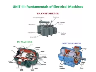
TURBO MACHINESUNIT-III Reaction Water Turbines Dr. Pramod B. Salunkhe
Overview • Classification • Franis turbine • Kaplan turbine • Velocity diagrams • Draft tube • Degree of Reaction • Cavitation • Performance characteristics
Principle of Operation • Water enters the turbine and glides over the blades • Both kinetic and pressure energies are used to transfer momentum • Pressure reduces from inlet to exit of turbine, hence air-tight casing is required
Classification of Reaction Turbines • Radial Flow Reaction Turbine i. Inward radial flow turbine -Water flows from outward to inward ii. Outward radial flow turbine -Water flows from inward to outward 2. Axial Flow Reaction Turbine -Water flows parallel to the axis of shaft 3. Mixed Flow Reaction Turbine -water enters axially and leaves radially or vice-versa
Francis Turbine • Developed by James Francis • Works under medium head (50 m – 150 m) and medium discharge condition
Components of Francis Turbine • Runner – to absorb momentum from the flow of water • Inlet Guide Vanes – to guide water at correct angle and control the flow rate of water • Casing- to convert kinetic energy of water into pressure energy • Draft Tube- to increase the pressure energy at the exit so as to allow turbine to locate above the tail race