Download
1 / 1
30 likes | 300 Views
Synchronous Buck Converter with Output Impedance Correction Circuit (OICC). V. Švikovi ć.

E N D
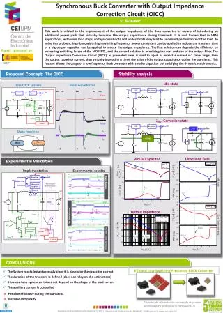
Synchronous Buck Converter with Output Impedance Correction Circuit (OICC) V. Šviković This work is related to the improvement of the output impedance of the Buck converter by means of introducing an additional power path that virtually increases the output capacitance during transients. It is well known that in VRM applications, with wide load steps, voltage overshoots and undershoots may lead to undesired performance of the load. To solve this problem, high-bandwidth high-switching frequency power converters can be applied to reduce the transient time or a big output capacitor can be applied to reduce the output impedance. The first solution can degrade the efficiency by increasing switching losses of the MOSFETS, and the second solution is penalizing the cost and size of the output filter. The Output Impedance Correction Circuit (OICC), as presented here, is used to inject or extract a current n-1 times larger than the output capacitor current, thus virtually increasing n times the value of the output capacitance during the transients. This feature allows the usage of a low frequency Buck converter with smaller capacitor but satisfying the dynamic requirements. OICC Project sponsored by FAST* • Proposed Concept: The OICC Stability analysis Idle state The OICC system Ideal waveforms ZOUT Correction state State machine Close-loop Gain Virtual Capacitor Experimental Validation Implementation Experimental results Basic System Output impedance The OICC System Basic System The OICC – zoom load step-up CONCLUSIONS • The System reacts instantaneously since it is observing the capacitor current • The duration of the transient is defined (does not relay on the estimations) • It is close-loop system so it does not depend on the shape of the load current • The auxiliary current is controlled Efficient Low-Switching-Frequency BUCK Converter • Penalize efficiency during the transients • Increase complexity *Fuentes de alimentación con rápida respuesta dinámica para gestión dela energía (FAST)