Reset Sources and Watchdog Timer
Reset Sources and Watchdog Timer. Reset Sources . A Reset sets all I/O Registers to their initial values, and the program starts execution from the Reset Vector (=0X0000 or the start of Boot Loader depending on Boot Reset Fuse ).


Reset Sources and Watchdog Timer
E N D
Presentation Transcript
Reset Sources • A Reset sets all I/O Registers to their initial values, and the program starts execution from the Reset Vector (=0X0000 or the start of Boot Loader depending on Boot Reset Fuse). • The MCU Control and Status Register (MCUCSR) provides information on which reset source caused the Reset.
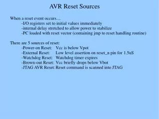
Power-on Reset: The μC resets when: • the supply voltage<Power-on Reset threshold (≈1.3V) • and is meant to trigger the Start-up Reset, as well as to detect a failure in supply voltage. Thereby MCUCSR-Bit 0 is set. • External Reset: The μC resets when a ‘0’ is applied to the RESET pin for 1.5μs Thereby MCUCSR-Bit 1 is set. • Brown-out Reset: The μC resets when the supply voltage<the Brown-out Reset threshold (typically 2.6 when BODLEVEL = 1 or 4V when BODLEVEL = 0 ) and the Brown-out Detector is enabled. Thereby MCUCSR-Bit 2 is set.
Watchdog Reset: The μC resets when the Watchdog Timer period expires and the watchdog is enabled. Thereby MCUCSR-Bit 3 is set. • JTAG AVR Reset to enable JTAG testing with port pins in high-z state. Thereby MCUCSR-Bit 4 is set. • Note that: • Bits 1 to 4 of the MCUCSR are reset by a Power-on Reset, or by writing a logic zero to the flag. • Bit 0 is reset only by writing a logic zero to the flag.
Internal Voltage Reference • It has a nominal voltage of 1.23V and is used by: • The Brown Out Detection (BOD). • The A/D (amplified to 2.56V). • It can also be used as an input to the analog comparator. • It consumes 10uA and should be disabled when not needed in sleep modes.
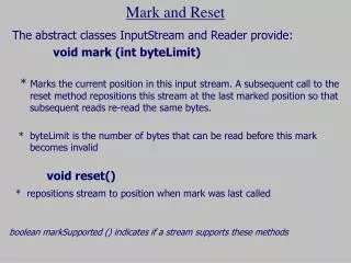
Watchdog Timer • By controlling the Watchdog Timer prescaler, the Watchdog Reset interval can be adjusted, and if the reset period expires without another Watchdog Reset, the μC resets and executes from the Reset Vector. • The WDR –instruction resets the Watchdog Timer. • The Watchdog Timer is clocked from a separate On-chip Oscillator which runs at 1 MHz. • To reset the Watchdog timer the following assembly instruction need to be embedded in the program loop: • #asm("wdr")
Watchdog Timer The chosen prescalar must be chosen according to the duration of the program loop
Enabling the Watchdog: • By letting Watchdog Enable bit WDE=1 the Watchdog Timer is enabled without any restriction. • To prevent unintentional disabling of the Watchdog, a special turn-off sequence must be followed when the Watchdog is disabled. • Disabling the Watchdog: • In the same operation, write ‘1’ to WDTOE and WDE (A logic one must be written to WDE even though it is set to one before the disable operation starts). • Within the next four clock cycles, write a logic 0 to WDE. This disables the Watchdog.