
Objective
E N D
Presentation Transcript
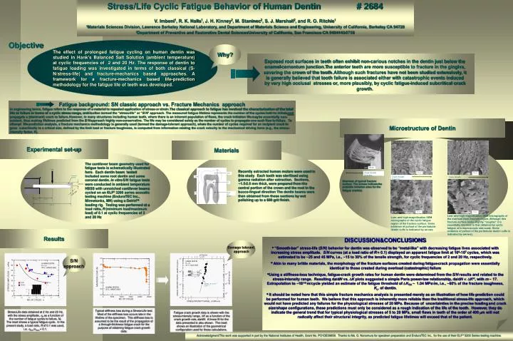
Enamel b Load M Crown a h Enamel corner Pulp Fatigue background: SN classic approach vs. Fracture Mechanics approach In engineering terms, fatigue refers to the response of a material to repeated application of stress or strain.The classical approach to fatigue has involved the characterisation of the total life to failure in terms of a cyclic stress range, and is often termed the “stress-life” or “S/N” approach. The measured fatigue lifetime represents the number of the cycles both to initiate and propagate a (dominant) crack to failure. However, in many structures including human teeth, where there is an inherent population of flaws, the crack initiation life may be essentially non-existent, thus making lifetimes predicted from the S/N approach highly non-conservative. The life may be considered solely as the number of cycles to propagate one such flaw to failure. To attempt life-prediction analysis, a fracture mechanics methodology is generally used (termed the damage-tolerant approach), where the number of cycles required for an incipient crack to grow subcritically to a critical size, defined by the limit load or fracture toughness, is computed from information relating the crack velocity to the mechanical driving force (e.g., the stress-intensity factor, K). (a) (a) 10 m 0.90 mm 10 m Crack Growth Direction Crack Growth Direction Dentin (with tubules) Root da/dN = 5.1 x 10⁻¹¹ (K)17.3 4 mm 2 mm 100 m 10 mm Crack Growth Direction 108 107 104 105 106 103 102 The cantilever beam geometry used for fatigue tests is schematically illustrated here. Each dentin beam tested included some root dentin and some coronal dentin. In vitro S/N fatigue tests were conducted in ambient temperature HBSS with unnotched cantilever beams cycled on an ELF 3200 series acoustic testing machine (EnduraTEC Inc., Minnetonka, MN) using a DelrinTM loading rig. Testing was performed at a load ratio, R (minimum load/maximum load) of 0.1 at cyclic frequencies of 2 and 20 Hz Recently extracted human molars were used in this study. Each tooth was sterilised using gamma radiation after extraction. Sections, ~1.5-2.0 mm thick, were prepared from the central portion of the crown and the root in the bucco-lingual direction The dentin beams were then obtained from these sections by wet polishing up to a 600 grit finish. (b) (b) 10 m 10 m max m a min , Nf . Why? The effect of prolonged fatigue cycling on human dentin was studied in Hank’s Balanced Salt Solution (ambient temperature) at cyclic frequencies of 2 and 20 Hz. The response of dentin to fatigue loading was investigated in terms of both classical (S-N/stress-life) and fracture-mechanics based approaches.A framework for a fracture-mechanics based life-prediction methodology for the fatigue life of teeth was developed. Exposed root surfaces in teeth often exhibit non-carious notches in the dentin just below the enamel-cementum junction.The anterior teeth are more susceptible to fracture in the gingiva, severing the crown of the tooth. Although such fractures have not been studied extensively, it is generally believed that tooth failure is associated either with catastrophic events induced by very high occlusal stresses or, more plausibly, by cyclic fatigue-induced subcritical crack growth. Objective Microstructure of Dentin Experimental set-up Materials Overview of typical fracture surface. The arrows indicate the probable initiation sites for the fatigue crack(s) Stress/Life Cyclic Fatigue Behavior of Human Dentin # 2684 V. Imbeni1, R. K. Nalla1, J. H. Kinney2, M. Staninec2, S. J. Marshall2, and R. O. Ritchie1 1Materials Sciences Division, Lawrence Berkeley National Laboratory, and Department of Materials Science and Engineering, University of California, Berkeley CA 94720 2Department of Preventive and Restorative Dental SciencesUniversity of California, San Francisco CA 9494143-0758 Low- and high-magnification SEM micrographs of the overload (fast) fracture region. Although this fracture surface looks slightly “rougher” it is essentially identical to that obtained by cyclic fatigue, at a macroscopic size-scale. Some evidence of pullout of the peritubular dentin cuffs is indicated by arrows). Low- and high-magnification SEM micrographs of the cyclic fatigue region of the fracture surface. Some evidence of pullout of the peritubular dentin cuffs is indicated by arrows. Results • DISCUSSION&CONCLUSIONS • “Smooth-bar” stress-life (S/N) behavior for dentin was observed to be “metal-like” with decreasing fatigue lives associated with increasing stress amplitude. S/N curves (at a load ratio of R = 0.1) displayed an apparent fatigue limit at 106-107 cycles, which was estimated to be ~25 and 45 MPa, i.e., ~15 to 30% of the tensile strength, for cyclic frequencies of 2 and 20 Hz, respectively. • Akin to many brittle materials, the morphology of the fracture surfaces created during fatigue-crack propagation were essentially identical to those created during overload (catastrophic) failure • Using a stiffness-loss technique, fatigue-crack growth rates for human dentin were determined from the S/N results and related to the stress-intensity range. Resulting da/dN vs. DK plots suggested a simple Paris power-law relationship, da/dN DKm, with m ~ 17. Extrapolation to ~10-10 m/cycle yielded an estimate of the fatigue threshold of DKTH ~ 1.04 MPam, i.e., ~60% of the fracture toughness, Kc, of dentin. • It should be noted here that this simple fracture mechanics analysis is presented merely as an illustration of how life prediction could be performed for human teeth. We believe that this approach is inherently more reliable than the traditional stress-life approach, which would not have predicted any failures for the physiological stresses of 20 MPa. Because of uncertainties in the precise loading and crack size/shape configurations, these predictions must only be considered as a rough indication of the life of the tooth. However, they do indicate the general trend that for typical physiological stresses of 5 to 20 MPa, small flaws in teeth of the order of 400 mm will not radically affect their structural integrity, as predicted fatigue lifetimes will exceed that of the patient. Damage tolerant approach S/N approach Typical stiffness loss during a Stress-Life test. Most of the stiffness loss occurs late in the lifetime of the specimen. This stiffness loss is assumed to be the result of the propagation of a through-thickness fatigue crack for the purpose of obtaining fatigue crack growth data. Stress-Life data obtained at 2 Hz and 20 Hz, with the stress amplitude, a as a function of the number of fatigue cycles to failure, Nf. The inset shows a typical fatigue cycle. In the present study, a load ratio, R of 0.1 was used, i.e. min/max = 0.1. Fatigue crack growth data is shown with the stress-intensity range, K as a function of the crack growth rate, da/dN. A linear fit for the data presented is also shown. The inset shows an illustration of the geometrical configuration used for these calculations. Acknowledgment:This work was supported in part by the National Institutes of Health, Grant No. PO1DE09859. Thanks to Ms. G. Nonomura for specimen preparation and EnduraTEC Inc., for the use of their ELF 3200 Series testing machine.