Advancing 6D Muon Cooling: HCC Technology Investigation
Explore the feasibility of 6D muon cooling for collider projects through engineering demonstrations and experiments. Investigate the Helical Cooling Channel (HCC) concept for high average gradient and reduced decay losses.

Advancing 6D Muon Cooling: HCC Technology Investigation
E N D
Presentation Transcript
MCTF EXPERIMENTAL ACTIVITES - towards demonstrating 6D cooling Andreas Jansson MUTAC Meeting 8-10 April 2008 1
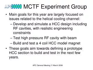
MCTF Experimental Goals • Goal: Establish feasibility of 6D muon cooling required for collider. • Want to bring (at least) one cooling channel technology to the point where • Enough engineering has been done that we are confident it can be built. • Simulations show that what we can build would actually cool. • We would then like to build a suitable section as an engineering demonstration, eventually followed by a 6D cooling experiment. • Cost estimate for engineering demo is $3-5M. • As an initial goal: Investigate the Helical Cooling Channel (HCC) proposed by Derbenev & Johnson (Muons Inc): • Investigate HPRF behavior in beam. • Find a realistic way to incorporate RF into the HCC Focus of this talk Andreas Jansson MUTAC Meeting 8-10 April 2008 2
The bigger picture (See Palmers talk) This is the part we are focusing on Andreas Jansson MUTAC Meeting 8-10 April 2008 3
Why focus on HCC? • Possibility of high average gradient yielding fast cooling and less decay losses. • Concept needed further study. • Guggenheim already being studied by NFMCC. 200MHz RF K. Yonehara Andreas Jansson MUTAC Meeting 8-10 April 2008 4
Beam tests of High pressure RF Cavities Andreas Jansson MUTAC Meeting 8-10 April 2008 5
MTA beamline • HCC uses high pressure H2 cavities • Test with beam critical to understand if HPRF cavities are useful. • MTA beam line major activity and budget item for MCTF this year. • See separate talk (Johnstone) Andreas Jansson MUTAC Meeting 8-10 April 2008 6
First HPRF experiment Beam simulation • Beam tests will be done in collaboration with Muons Inc • First test will use the existing Muons Inc test cell • Will indicate direction of follow-ups experiments • Linac 400MeV proton beam can generate ionization levels similar to muon beam. • 6e12 protons ~1.2e13 muons beam Muons Inc test cell Andreas Jansson MUTAC Meeting 8-10 April 2008 7
Cavity Cavity Vrf + Vrf = 0 Neutral positive deltaZ Vrf - Vrf = 0 What we expect to see? • If re-absorption time is long enough, electrons would load down the cavity. • Effect increasing along linac pulse • Estimates depend on hydrogen purity and vary by orders of magnitude • Try adding e.g. SF6 • Limited diagnostics • Power probe • Field probe A.Tollestrup Andreas Jansson MUTAC Meeting 8-10 April 2008 8
Follow-up cavity • Test cell is not an accelerating cavity. • Several effects we will not be able to study • Scaling with pressure • Are the ions a problem? • Build dedicated cavity! • Will require MCTF resources in FY09. • Scale ~1 FTE + ~$200k • There is also a SBIR Phase I with Muons Inc. M. Popovic Tunable HP cavity Andreas Jansson MUTAC Meeting 8-10 April 2008 9
HPRF summary • MTA beamline installation major activity in FY07-08. • Plan to complete first HP cavity test by end CY08. • Requires MTA beamline completions, which is contingent on LINAC access possibility (shutdown now moved to CY09). • Follow up with dedicated cavity in FY09. Andreas Jansson MUTAC Meeting 8-10 April 2008 10
How to Incorporate RF in HCC Andreas Jansson MUTAC Meeting 8-10 April 2008 11
Balbekov’s HCC “rules of thumb” • Independent analysis by Balbekov has confirmed Yonehara’s main simulation results, and in addition provided some rules of thumb: • Equilibrium emittance is proportional to helix period. • 1-2mmrad at 1m helix and 250MeV/c • Generally higher in HCC than e.g. Guggenheim for comparable magnetic field because of weaker focusing at absorber • There is an optimal RF frequency for each helix period. The cavity size roughly scales with the helix period. • 200MHz @ 1m, 400MHz @ 50cm, etc • Engineering more challenging than in previously simulated cases. • Obtainable 6D cooling factor (ratio of acceptance and equilibrium emittance) with fixed helix period is about 90 in ideal case. • Further cooling requires shorter helix (higher B field and RF frequency). Andreas Jansson MUTAC Meeting 8-10 April 2008 12
Magnet design • HCC requires superimposed solenoid, helical dipole and helical quadrupole fields • Helical solenoid (HS) use smaller coils than a “traditional” design • Lower peak field • Less stored energy • Lower cost • Field components in HS determined by geometry • Over constrained • Coil radius is not free parameter V.Kashikin Andreas Jansson MUTAC Meeting 8-10 April 2008 13
How to implement a real HCC? “Type I” “Type 2” “Type 3” • RF and coils separated • Lower RF packing factor • Likely easier to build and maintain. • Requires good matching between sections • RF between coils • Lower RF packing factor. • Difficult H2 cryostat design and assembly • RF inside coil • Highest possible RF • packing factor • Cavity must be smaller than the coil → high frequency Andreas Jansson MUTAC Meeting 8-10 April 2008 14
HCC Type I simulations • Rcavity =56cm, Rcoil=50cm, 4000x cooling factor • More realistic, but still Rcavity > Rcoil. • What happens when reducing the cavity size further? K. Yonehara LEMC’07 Andreas Jansson MUTAC Meeting 8-10 April 2008 15
Reducing cavity size • Initial and final emittances for different frequency cavities (fixed coil diameter). • Green arrow indicates where Rcavity = Rcoil • 10% smaller cavity seems OK • 20% smaller cavity does not cool K. Yonehara Andreas Jansson MUTAC Meeting 8-10 April 2008 16
Stress simulation of helical pressure vessel At 1500PSI (100atm) SS316: 1.25” wall required Inconel 625: 0.75” wall required ASME pressure vessel code used A.Lee Andreas Jansson MUTAC Meeting 8-10 April 2008 17
Required clearance • Coil and cavity at different temperatures require insulating vacuum gap. • Estimated required clearance ~3” • This does not include any RF feed • Compare to HP H2 cavity radius at various frequencies • Only 200MHz version appear to be plausible. • Balbekovs results imply high equilibrium emittance. coil ~0.8” coil support 0.4” – 1” ~3” insulating vacuum HP cavity ~1.25” pressurized H2 (assuming 200atm H2 ) Andreas Jansson MUTAC Meeting 8-10 April 2008 18
8 Rings per Helix Period 50% Free Space RF between coils • Coils can be separated to allow space for cavities without compromising field. • Similar clearance requirements would likely apply longitudinally. • Very short helix periods appear impractical. • Balbekovs results imply high equilibrium emittance. • Lower RF packing factor implies slower cooling • Need further study S.Kahn Δ Andreas Jansson MUTAC Meeting 8-10 April 2008 19
Separate RF and helical solenoid • Observed problem: time-of-flight spread in helical section too large for longitudinal stability. • To be efficient, would need a short matching section. • Lower RF packing factor implies slower cooling. • Current matching design adds significant length. • Solution may exist, but not found yet. K. Yonehara Andreas Jansson MUTAC Meeting 8-10 April 2008 20
HCC Status • We now have a bottom-up estimate of the engineering clearances required for a HCC based on a Helical Solenoid. • Simulations of the simplest Type I (cavity inside coil) HCC obeying these constraints indicate loss of cooling • Possibly with the exception of 200MHz version, which can not go all the way to the required emittance. • There are plenty of ideas left, which will be investigated in the near future. Andreas Jansson MUTAC Meeting 8-10 April 2008 21
Example of Modified Helical Solenoid HCC • Adding more coils to the Helical Solenoid could relax the geometrical constraints and allow to widen the primary coil • Overall solenoid could allow independent tuning of Bz component • Additional helical correction coil(s) could give further tuning range of quad component. • Dielectrics inside the cavity could reduce cavity size Primary helix coil RF cavity Correction coil Correction coil K. Yonehara Andreas Jansson MUTAC Meeting 8-10 April 2008 22
Preliminary result HCC with correction coils • Preliminary study using • 300MHz cavities • 1.6m helix period. • 8cm radial clearance between cavity and coil • Seems to work in simulation! • Need to investigate: • extension to higher frequency & shorter periods. • optimal correction coil scheme. K. Yonehara Work in progress Andreas Jansson MUTAC Meeting 8-10 April 2008 23
Near Term Plans • Finish MTA beamline and test HPRF cavity with beam. • Continue efforts on including RF in HCC, looking for solution that can be extended to shorter periods and higher frequencies (=low emittance). • If a promising solution is found: proceed to engineer, build and test a section of HCC with RF. • If no promising solution can be found, move on to consider e.g. FOFO “snake” or Guggenheim. • Work out a coordinated NFMCC/MCTF experimental plan between now and August. Andreas Jansson MUTAC Meeting 8-10 April 2008 24