Download
1 / 30
300 likes | 446 Views
Report on technical study of TSR@ISOLDE. Outline Beam-line layout Storage time REXTRAP Upgrade of charge breeder Technical integration study Conclusions. Fredrik Wenander, TSR workshop 14/2-2014. Test Storage Rings at Heidelberg. * In operation since 1988

E N D
Report on technical study of TSR@ISOLDE Outline Beam-line layout Storage time REXTRAP Upgrade of charge breeder Technical integration study Conclusions Fredrik Wenander, TSR workshop 14/2-2014
Test Storage Rings at Heidelberg * In operation since 1988 * Mainly for atomic physics studies and accelerator development * One nuclear physics experiment – FILTEX (internal polarized H2 gas target) Multiturn injection: mA current Electron cooler: transverse Tcool in order of 1 s RF acceleration and deceleration possible Typicalenergy12C6+: 6 MeV/u Circumference: 55.42 m Vacuum: ~few 1E-11 mbar Acceptance: 120 mm mrad experiment resonator ECOOL extraction injection
Building layout Presently at MPI-K, Heidelberg, a large hall is housing the TSR with enough space around it for experiments and equipment that need to be close to the ring. The basement underneath the ring is used for power supplies and other necessary equipment. service tunnel 36m 26m 10m (7m between floor and crane hook) Proposed layout to fit the TSR: Installation above the CERN service-tunnel Tilted beamline coming up from the machine. 4.73m above Isolde hall floor 4 Courtesy E. Siesling
Building layout TSR building 670: Taken in account at the construction of the new user building 508. Water station: Water station and cooling tower to be integrated in the ISOLDE area. Roads: Adaptation of the Route Rutherford and corner with Route Einstein. Move of the ramp giving access to the premises to the Route Democrite side. CERN service tunnel: Construction above the tunnel creating two separate basements to house TSR equipment racks and power supplies. 670 3m Service tunnel 508 Courtesy E. Siesling
Beam-line layout 35 m 4.15 m • Numerous updates • Larger hall dimensions 25*35 m2 • Ring position shifted • -> more space for in-ring exp. • 3. Standardization -> HIE-HEBT • elements for inj. & ext. lines • 4. Technically and beam-optically • feasible • 5. Two experimental stations • for extracted beam • 6. No beam-line back to ISOLDE 6.86 m 12.73 m In-ring experiment 25 m
Injection line 35 m 4.15 m 6.86 m • Links HIE-ISOLDE to TSR ring via XT04 • Considers HIE-ISOLDE and TSR • floor level difference of 4.73 m • Includes the move of the • experimental station XT03 to the XT05 position • Additional equipment required6 dipoles • 19 quadrupolessinglets • 8 steerers • 10 beam diagnostics boxes 12.73 m 25 m Injection septum horizontal achromat existing at Heidelberg XT04 XT05 vertical achromat CERN input: A. Parfenova, D. Voulot, B. Goddard, M. Fraser 7
Extraction lines 35 m • * Tentative layout for two experimental stations. • * Tolerated stray magnetic field at ring from experiments • * Beam optics study initiated. • * Awaiting feedback from physics community. 4.15 m 6.86 m 12.73 m 25 m Injection / Extraction septum existing at Heidelberg CERN input: A. Parfenova, D. Voulot, B. Goddard, M. Fraser 8 8
Position of in-ring experiment 35 m 4.15 m Position at Heidelberg 6.86 m 12.73 m In-ring experiment 25 m M. Grieser Benefits of change 1. Smaller -function smaller beam size lifetime increase with in-ring target 2. Small dispersion in the RF region beam position independent of beam energy easy to hit the target 3. Advantageous for storage of multiple charges avoid betatron oscillations and beam losses Beam dimensions: Rearrangement of optics lattice required Injection septum e-cooler Target station Beam profiler RFsystem = New exp. position 9 9 9
Storage time REXTRAP? * Ring injection repetition rate T_rep_rate < 5 Hz * T_rep_rate < 0.5 Hz not unusual due to e-cooling and/or in-ring beam exploitation EBIS breeding time Tbreed < Trep_rate in many cases + ample time to reach high charge states - keep them in 1. REXEBIS or 2. REXTRAP q+ dependent A 0 50 100 150 200 250 REXTRAP cyclotron resonance frequency We know that space-charge effects modifies c (can be adapted for) transmission efficiency decreases Holding time in REXTRAP? • 60Ni+ and 87Rb+ kept for >1.5 s • Additional losses <20% • 3E7 ions/s injected number of ions
Storage time REXTRAP? The concerns A. Short-lived ions B. Noble gases and ions with high ionization potential such as F, Cl, Br Reason? Charge exchange with buffer-gas Ne cooling gas P. Delahaye et al., Nucl Phys A746 (2004) 604 C. Trapping efficiency in REXTRAP of radioactive ions WITCH experiment has recorded storage times for 35Ar of 0.7 * 1/2 (space-charge dependent?) Vague memory of similar effects in REXTRAP Reason? Shake-off electrons cause radiative and di-electronic recombination? Tests with radioactive ions foreseen for the summer 2014
Charge states out of REX REXEBIS breeding times for a selection of elements of relevance for TSR@ISOLDE experiments • Rigidity TSR • Storage lifetimes • Cooling times • Experiments • All benefit from high q * to be tested • G. Schiwietz and P. L. Grande, Nucl. Instrum. Meth B175 (2001) 125 REXEBIS capable of producing sufficiently low A/q (or beam rigidity for < 10MeV/u) for almost all elements But some experiments might require: * Fully stripped to Z~70 * Few-electron system, e.g. for Th/U Estimated attainable charge states in REXEBIS and after stripper foil as a function of ion Z
TSR@ISOLDE implications for the HEC2 Courtesy A. Shornikov * After Z=60 the abundance of bare state will drastically drop ** Only Li-like Tl with acceptable abundance *** Assumed an injection repetition rate of 1 Hz
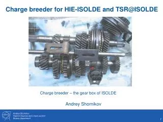
Need a very different breeder Design parameters HIE-ISOLDE / TSR@ISOLDE breeder * Capacity of 108 primary ions needs current Ie >3 A , Transverse acceptance ~ 34 μm (REXEBIS) needs Ie ~ 4-5 A
No such breeders available rep - reported, est - estimated, * - in commissioning phase † - discontinued Bubble size represents electron current Courtesy A. Shornikov
Good news we not alone in the upper right corner! Courtesy A. Shornikov Bubble size represents electron current
How we are addressing them Influence of B field leaking High Energy Current and Compression (HEC2) electron gun project Requirements compared to simulations Matching two focusing systems Very laminar electron flow, high electrostatic compression anode electron beam cathode Pikin, E. N. Beebe, and D. Raparia, Rev. Sci. Instr. 84 033303 (2013) HEC2 designed at BNL is now a collaborative effort between BNL and CERN
HEC2 prototype tests at BNL First beam time – 08.11.2013-15.11.2013 Anode voltage Extracted current (1V=1A) Prototype gun design by BNL, built by CERN being tested at BNL by joint team at BNL TEBIS * These activities supported by HIE-ISOLDE design study will continue in 2014 * Hopefully a continuation within ENSAR2
Technical integration study * Study group E. Siesling, E. Piselli, F. Wenander • Mandate - areport covering the following aspects should be prepared: • An inventory of all equipment to be brought to CERNfor installation. • Initial estimates for the infrastructure needed for the ring and it’s transfer lines. This should include the overall space, power, cooling and safety needs. It should not include a detailed design of these systems. • For each system a brief study of the equipment to be installedshould be undertaken after discussion with the experts in Heidelberg and the concerned CERN groups. This study should include: • The issues associated with the integration of the equipment into the CERN accelerator environment. • The spare situationfor the equipment together with any issues or recommendation concerning additional spares. • A radiological assessment of the equipment in collaboration with RP. • The control system presently used for the system and whether the control hardware must be replaced to meet CERN standards. • Any specific costs associated with the initial installation, or the modification to meet CERN standards should be estimated. * Study running Sep 2012 to Aug 2013
Technical integration study Study covers the injection line from HIE-ISOLDE to TSR and the associated costs. Assumes that a 3rd beam line XT03 exists, which is modified to TSR. in-ring experiments Study does not cover the cost of extraction line(s); only presents possible layouts. Study does not cover in-ring experiments electron target gas-jet target Study does not cover an upgrade of REXEBIS which is needed for some physics cases. extraction lines Assumptions and limitations injection line XT05 XT03 23
Technical integration study * Divided into 18 work packages. * Full equipment inventory. * TSR elements evaluated by CERN specialists -> CERN recommendations. * In general a positive response and supportive response from the CERN groups. Two approaches 1. CERN homologation (full-fledged ‘standardization’) 2. Keep-system-as-is (low-budget option with minimal changes) * Preliminary results presented at IEFC 31/7-2013. * Final report to Director of accelerators and Department leaders 28/8-2013. * Full presentation (140 pages) and executive summary (15 pages) can be obtained upon request (from F. Wenander).
Work package key actions and CERN recommendations Work package Key action / recommendation Civil engineering and infrastructure * Initial study performed for building and services. Alignment * Do the alignment using external targets instead of in beam line as at Heidelberg. Control system and applications * Replace existing control system; use CERN CO infrastructure and separate the equipment control for different groups. Magnets * Keep the magnets but perform a refurbishment, install electrical protection and external targets. Power supplies and HV installations * Refuse all existing power supplies and equipment and use standard HIE-ISOLDE / LHC / CERN general solutions. Vacuum * Accept most material, complement with spares and replace bakeout system. Beam diagnostics * Accept most instruments; replace electronics; improve sensitivity for Schottky, FC and beam profile measurement. RF * Exchange all RF equipment for copies of ELENA/AD; use a Finemet type cavity. E-cooler * Accept e-cooler as is; refurbish magnets and HV equipment.
Work package key actions and CERN recommendations • Injection-extraction septum * Accept septum as is; complement HV supplies and HV equipment. • Scrapers * Remove as presently not used and keep for possible use in the future. • Induction accelerator * Accept as is; no real CERN expertise. • TSR injection line * Follow HIE-ISOLDE design layout; optics study performed. • Extraction lines * Beam optics study in progress. • In-ring experiments * Outside the scope of this study. • General safety * The missing electrical protection of magnet connections has the highest priority. • Radioprotection * No activation of the machine has been measured and there should be little concern for importing the ring. Future operation conditions similar to HIE-ISOLDE linac. • Dismantling and Reassembly * Bulk of dismantling and transport covered by • TSR@ISOLDE collaboration; reassembly mainly done by each work package; integration important as outdated or incomplete drawings.
Cost, manpower and risk summary Keep-system-as-is • 1. These values indicate the reduction in cost compared to the CERN integration proposal. Negative value = saving; Positive value = increased expense. • 2. These values indicatethe required manpower for the Keep-system-as-is, not the reduction in manpower compared to the CERN integration proposal. • 3. 1 – low risk, 5 – high risk. 28
Technical integration study - conclusions * The radiological concern of importing the ring is minimal. * Well advanced civil engineering plan with associated infrastructure exists. * No technical show stoppers for the implementation – standard solutions identified. Keep-system-as-is CERN integration proposal a. First cost and manpower estimate believed to be conservative. The CERN support groups claim that the cost of some WPs can be reduced if the allocated budget so requires. However, no contingency included. b. Most CERN groups have insisted on hardware changes and CERN standardization and discourage a 3 years transition period with temporary solution as that would inflate the costs. Total cost and manpower for transfer and integration into a CERN facility: 15.2 MCHF 27.5 FTE (man year) a. Would need to keep all subsystems as they are since many are interlinked with the control system. b. Would have limited / no support by CERN groups; longer dependence on MPIK Heidelberg. c. Power converters, vacuum, magnets, RF and e-cooler could in principle be imported as such. d. Improved electrical ring safety is mandatory if the ring is imported as is. The approximate cost and manpower need for the Keep-system-as-is scenario are: 11.8 MCHF 17.1 FTE (man year) The cost saving might appear low. Reasons: * The main cost drivers are the injection line, buildings and infrastructure. * Some spares, complementing parts and replacement parts are absolutely necessary. * Includes the mandatory electrical protection of magnets connections. * Includes sensitivity improvement of the beam diagnostics.
General conclusions • * The technical aspects of the integration have been studied. No technical show stoppers identified. • * Cost and manpower analysis of the integration has been performed. • * Request feedback from the user community about the layout of the extraction lines and experimental setups. • * Tests of charge breeder upgrade on-going. Concept promising but a long way to go! • * Influence of radioactive decay on the storage time inside REXTRAP to be investigated.