Download
1 / 15
150 likes | 319 Views
單元三:單相電流控制變流器. 變流器模型推導. 學習內容. 全橋式電壓源變流器工作原理. 電感電流控制原理. 正弦式 PWM 原理. 瞬時電壓控制原理. i o. II ( P o <0). I ( P o >0). v o. (TA+,DB+). i o. (TA+,TB-). (DA-,DB+). (DA-,TB-). v o. (DA+,TB+). (TA-,TB+). (DA+,DB-). I. (TA-,DB-). IV. II. III. IV ( P o <0). III ( P o >0).

E N D
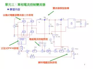
單元三:單相電流控制變流器 變流器模型推導 • 學習內容 全橋式電壓源變流器工作原理 電感電流控制原理 正弦式PWM原理 瞬時電壓控制原理
io II (Po<0) I (Po>0) vo (TA+,DB+) io (TA+,TB-) (DA-,DB+) (DA-,TB-) vo (DA+,TB+) (TA-,TB+) (DA+,DB-) I (TA-,DB-) IV II III IV (Po<0) III (Po>0) Inverter mode Po>0 Rectifier mode Po<0 • 交流電路瞬時工作象限 • 全橋式電壓源變流器工作原理 • 工作模式 • 八種開關導通狀態
(I) Bipolar voltage switching • 正弦式PWM原理 • Magnitude modulation index • Frequency modulation index • Fundamental voltage (ma1) • Harmonic voltage mf is better to be odd for odd and half-wave symmetric • Bipolar voltage switching
(II) Unipolar voltage switching • 正弦式PWM原理(續) • Unipolar voltage switching • Harmonic voltage • Advantages over the bipolar switching • Switching frequency is increased one time equivalently • The voltage fluctuation is only Vd which is one half of the bipolar switching
N vconB = -vconA = -vcon (uniploar) SB = 1 – SA (bipolar) or L + io Load C A Vd Icap B - iL • 變流器模型推導 : Switching function of A and B legs (i = A, B) (The same for uniploar and bipolar) (Voltage gain of inverter) where
L + C Load A Vd { B - Drive Circuits Sinusoidal PWM Trigging Signals Current Controller Control voltage io Voltage Controller Current command vc iL • 雙迴路控制架構 PC
Feedforward Control • 電感電流控制原理 電流內迴路 Feedback Control ks: Hall sensor gain (V/A) ui: Current loop bandwidth can be set by k1
瞬時電壓控制原理 Feedforward Control 電壓外迴路 kv: Voltage sensing gain Feedback Control 電流迴路頻寬較電壓迴路寬許多 可假設為理想 uv: Voltage loop bandwidth which is set by k2 and Should be much smaller than ui
實驗系統設計 • 系統參數 Vd = 100V, vtri=10kHZ/5Vp, ks = 0.2V/A, kv = 0.02 L = 3mH, C= 22uF, fs = 10kHz • 規格 ui = 1.25KHz = 2 1250 rad/s = 7854 rad/s uv = 300Hz = 1885 rad/s • 設計 kpwm = 100/5 = 20
電路連接及設定 1f-Inverter Input Power Power Module Load 50W 100VDC AD4 AD3 AD2 PCI-6025E A/D PWM [2 3 4] DA2 PC DA1
量測波形 (PC) iL