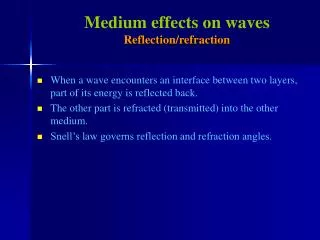
Diffraction Effects on Ultrasonic Waves
by Karim Jezzine and Alain Lhémery French Atomic Energy Commission CEA - Saclay. Diffraction Effects on Ultrasonic Waves Radiated by a Transducer Mounted on the Section of a Guide of Arbitrary Geometry. Context of development Theory brief review

Diffraction Effects on Ultrasonic Waves
E N D
Presentation Transcript
byKarim Jezzine and Alain Lhémery French Atomic Energy Commission CEA - Saclay Diffraction Effects on Ultrasonic Waves Radiated by a Transducer Mounted on the Section of a Guide of Arbitrary Geometry
Context of development • Theory • brief review • adaptation of Semi-Analytic F.E. method • Validation in the axisymmetric case • Transducer diffraction effects • influence of aperture/ bandwith in the axisymmetric case • 2D case: rectangular cross section • Summary – Work in progress
waveguide S z guide section guide axis transducer Context of development • industrial needs for simulation tools dealing with guided waves in CIVA(software platform for NDE simulation developed at CEA) • - prediction of transducer diffraction effects to optimise testing configuration (mode selection etc.) • - simulation of radiation, propagation, scattering by a defect and reception • aims: guides of arbitrary section computer efficiency => 3D computational methods hopeless • 1st application: unusual configuration of testing where the transducer (emitter/receiver) is mounted on the guide section
Context of development • Theory • brief review • adaptation of Semi-Analytic F.E. method • Validation in the axisymmetric case • Transducer diffraction effects • influence of aperture/ bandwith in the axisymmetric case • 2D case: rectangular cross section • Summary – Work in progress
modal decomposition : un , sn imposed end conditions: mixed or pure • find An knowing: mixed: either ux, uy,szz, or, sxz,syz,uzat z=0 pure: either ux,uy,uz, or sxz,syz,szz(e.g.: piezo transducer in direct contact)at z=0 • direct projection of the source terms on the mode basis impossible for pure end conditions minimisation of residual boundary values atz = 0 Gregory&Gladwell , Quart. J. Mech. Appl. Math. (1989) Puckett&Peterson, Ultrasonics (2005) Theory: brief review • basic idea: benefit of the symmetry of translation to restrict computations to the guide section modal decomposition propagation along z
Theory: brief review (contd.) • requirement: initial computation of modes- roots of analytical solutions (dispersion equation) for multi-layered plates or cylinders (expl. Disperse, NDT group at Imperial College)Lowe, I.E.E.E. Trans. UFFC (1995); + : « exact » dispersion equations – multi-layered - : two geometries only (plate, cylinder) • - Semi-Analytical Finite Element (S.A.F.E.) method: Dong&Nelson, J. Appl. Mech. (1972); Gavrić, J. Sound. Vib. (1995); Hayashi&Rose, Mat. Eval. (2003); Damljanović&Weaver, J. Acoust. Soc. Am. (2004); + : arbitrary section + easy to account for anisotropy, viscoelasticity - : computer intensive at high frequencies computation of modesin complex cases
meshing of the section by finite elements: elements: 1D (plate/axisym.) 2D (arbitrary section) • displacement field at the i-th element (for 2D case): • application of the principle of virtual work at the i-th element: z-propagator quadratic eigensystem (size 9x9) in k matrix of interpolation (quadratic) functions nodal displacement Theory: adaptation of SAFE to pb. of radiation from the section
Theory: adaptation of SAFE… (contd.) • assembly of a 3M x 3M quadraticeigensystem (M nodes) 1stelt. 2nd elt. (system #1) • once solved: • 6M eigenvalues (wavenumbers)- real values: propagative modes - imaginary values: evanescent ‘’ - complex values: inhomogeneous ‘’ • 6M eigenvectors (corresponding displacement)
Theory: adaptation of SAFE… (contd.) • account of source terms in SAFE:- existing: on the guiding surface • source modelled as an external force • Liu &Achenbach, J. Appl. Mech. (1995), Zhuang et al., J. Appl. Mech. (1999),Hayashi et al., J. Acoust. Soc. Am. (2003) • -here: on the section • problem closely related to that of the scattering from the free end of a semi-infinite guide: • SAFE: - Rattanawangcharoen et al., J. Appl. Mech. (1994), - Taweel et al., Int. J. Solids Struct. (2000), - Galan&Abascal, Int. J. Numer. Meth. Engng. (2002) • Le Clézio, PhD thesis Bordeaux 1 University (2001) • => source modelled as a vertical boundary condition
Theory: adaptation of SAFE… (contd.) • source mounted on the guide section at z = 0:- one selects modes (obtained from System #1) that make sense • for z > 0: 3M - stress tensor deduced from eigenvector displacement at the M nodes (xi , yi ) • - piston-source modelled as source of normal stress (system #2) i = 1,…, M • time-domain solutions obtained by Fourier synthesisin system#1, the various matrices are frequency-independent, not the overall system
Context of development • Theory • brief review • adaptation of Semi-Analytic F.E. method • Validation in the axisymmetric case • Transducer diffraction effects • influence of aperture/ bandwith in the axisymmetric case • 2D case: rectangular cross section • Summary – Work in progress
(System #1) + (System #2) + IFFT: z field points field prediction d transducer cylindrical guide • Simulation of a transducer in reception d d receiver output transducer E cylindrical guide transducer R Validation in the axisymmetric case
(very recent) example from Puckett & Peterson(Ultrasonics43(3), 2005) z • configuration: • - d = 25 mm • z = 250 mm- fused quartz- piston-like transd. • Gaussian pulses: 1107 kHz – 6.7 % of relative bandwidth(12 prop. modes) d transducer E cylindrical guide transducer R 40 60 80 100 120 140 40 60 80 100 120 140 measured(Ultrasonics43(3), 2005) simulated(present model) Validation in the axisymmetric case
Context of development • Theory • brief review • adaptation of Semi-Analytic F.E. method • Validation in the axisymmetric case • Transducer diffraction effects • influence of aperture/ bandwith in the axisymmetric case • 2D case: rectangular cross section • Summary – Work in progress
960 µs t aperture: point-source z field points Ø d aperture: Ø = 12.5 mm 400 µs t 0 d / 2 =12.5mm 0 d / 2 =12.5mm Transducer diffraction effects (axisym.) B-scans atz = 250 mm axial displacementuz (r,t) aperture: Ø = 25 mm 200 µs t 0 d / 2 =12.5mm
Transducer diffraction effects (axisym.) T and R : 12.5-mm-Ø T and R : 25-mm-Ø bw excitation pulse 6.7 % 20 % 40 %
Transducer diffraction effects (2D case) • Guide of rectangular cross-section 20x10mm (Steel) • 4 types of modes (2 axes of symmetry) • 11 propagative modes at f=200 kHz mode shape (Uz): 500 elements Flexural Y Flexural X Torsional Extensional
Transducer diffraction effects (2D case) extensional modes Group velocity (mm/s) Excitation pulse (fc=200kHz, bp=10%) : Frequency (MHz) rectangular: 20 x 10 mm² transducer E transducer R circular:Ø = 10 mm z=1m Ø = 10 mm
Transducer diffraction effects (2D case) Rectangular transducer Circular transducer
Context of development • Theory • brief review • adaptation of Semi-Analytic F.E. method • Validation in the axisymmetric case • Transducer diffraction effects • influence of aperture/ bandwith in the axisymmetric case • 2D case: rectangular cross section • Summary – Work in progress
Summary – Work in progress • Summary: • - SAFE method extended to case of transducer mounted on guide section: • - can deal with arbitrary guide (geometry, anisotropy) with symmetry of translation • - very efficient numerically (computation in the sole section, i.e. 2D or even 1D) • - validated by comparison with existing results for cylinder (theo. – exp.) • - importance of transducer diffraction effects: • - requires a proper simulation tool to be predicted • - easily studied using SAFE computations • - as stronghere as in the case of radiation from the guidingsurface • Work in progress: • - implementation in CIVA - scattering by a crack normal to the guide axis computed by SAFE • - experimental validation of our own
visco-elastic absorbing layer used to deal with sections of infinite extent: Hooke’s tensor in the absorbing layer hasan increasing (with r) imaginary part Liu & Achenbach, J. Appl. Mech. (1994) cement steel r Transducer diffraction effects: embedded guide • axisymmetry: still a 1D computation in the present case • no more real-valued wavenumbers, imaginary parts standing for the leakage of energy in the cement of propagative modes in the steel core.
L(0,1) L(0,2) L(0,3) L(0,4) 1049.8 m-1 818.9 m-1 562.1 m-1 471.4 m-1 1 1 1 1 1045.6 – 34.6 i m-1 819.0 – 8.5 i m-1 561.7 – 14.6 i m-1 471.7 – 6.2 i m-1 0 0 0 0 uz(r) -2.5 -3 -6 -3 a a a a 0 0 0 0 0 1.5 1.2 1 0 0 ur(r) 0 -2.5 -3 -0.2 -4.5 a a a 0 0 0 a 0 Transducer diffraction effects: embedded guide at z=0, 500 kHz – steel cylinder: free –embedded in cement
receiver output Ø 2a transducer E cylindrical guide transducer R = transducer E Transducer diffraction effects:aperture
aperture uz (r,t) ur (r,t) receiver output -9.3 dB -7.5 dB Transducer diffraction effects:aperture -9.9 dB
receiver output Ø d transducer R = transducer E transducer E cylindrical guide Transducer diffraction effects:aperture • Combination of effects of apperture in transmission and in reception and effects of relative bandwidth • 3 excitation pulses : • same center freq.: 1107kHz • 3 bandwidths: 6.7, 20, 40%
orthogonality relationFraser, J. Sound Vib. (1975) • pure end conditions: direct projection impossible z minimization of residual boundary values atz=0 guide axis Gregory&Gladwell , Quart. J. Mech. Appl. Math. (1989) Puckett&Peterson, Ultrasonics (2005) Theory: brief review(contd.) • mixed end conditions and axisymmetry:direct projection of the modes Duncan Fama, Quart. J. Mech. Appl. Math. (1972)Herczynski & Folk, Quart. J. Mech. Appl. Math. (1989)
+1.8 dB z field points Ø d -7.5 dB -9.3 dB Transducer diffraction effects:aperture t 960 µs B-scans atz = 250 mm radial displacementur (r,t) aperture: point-source aperture: Ø = 12.5 mm t 400 µs aperture: Ø = 25 mm t 200 µs 0 d / 2 =12.5mm 0 d / 2 =12.5mm 0 d / 2 =12.5mm
z Ø d aperture: Ø = 25 mm aperture: Ø = 12.5 mm aperture: point-source 40 60 80 100µs 120 140 160 Transducer diffraction effects:aperture received signal atz = 250 mm
(wavenumbers in m-1) mode: L(0,1) L(0,2) L(0,3) L(0,4) L(0,5) L(0,6) L(0,7) L(0,8) L(0,9) 5 elts 2058.4 1883.1 1753.1 1525.9 1174.2 1035.8 951.4 784.1 557.1 10 elts 2094.1 1884.1 1757.3 1548.9 1247.6 1047.7 988.1 866.1 619.8 S.A.F.E. 20 elts 2101.3 1884.2 1757.6 1550.5 1253.4 1049.4 991.3 870.2 623.4 30 elts 2101.9 1884.3 1757.6 1550.5 1253.6 1049.4 991.5 870.4 623.5 exact 2102.0 1884.3 1757.6 1550.5 1253.6 1049.4 991.4 870.4 623.4 0.06 ‰ error 10.6 % with 5 elements 0.1 ‰ error 0.6 % with 10 elements 0 % error 0.3 ‰ with 20 elements0 % error 0.16 ‰ with 30 elements Theory: validation vs. exact results • Cylindrical case: Pochhammer’s solution for wavenumbers(roots of an exact equation)here: 1MHz, steel cylinder of 20-mm-Ø – 9 propagative modes
0 -10 -20 amplitude in dB -30 -40 -50 -60 z/Ø 0 0.2 0.4 0.6 0.8 1 Transducer diffraction effects • Amplitude variation (z) of propagative, evanescent and inhomogeneous modes with imaginary part < 1500 m-1as radiated in the previous configuration at z = 250mm, only thepropagative modes contribute to the receivedsignal
6.7 % Transducer diffraction effects: excitation spectrum • Same center frequency, 3 different bandwidths bw excitation pulse simulated received signal 20 % 40 %