Download
1 / 33
330 likes | 448 Views
This document presents an overview of the mechanical analysis conducted on the SiD detector platform using ANSYS simulations. It details the design and models of the detector and mobile platform, emphasizing that the designs are simplified for computational efficiency. Key findings include various displacement outcomes under applied pressures, such as bending and twisting effects on the platform. The analysis employs A36 steel as a primary material, with essential parameters like Young’s Modulus and Poisson’s Ratio detailed. Future work aims to refine models for more realistic simulations.

E N D
SiD Platform Deformation Studies John Amann ILC Mechanical Engineering 11/21/06
Disclaimer: The designs and models for the detector, supports, and mobile platform used for the ANSYS simulations are crude at best and simplified to speed computation. The actual designs and subsequent performance may differ vastly. Scales are exaggerated on ANSYS contour plots for visual effect.
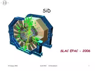
SiD SolidEdge 3D Model Detector, supports, and platform one complete unit made of A36 steel. Young’s Modulus =30e6 PSI Poisson’s Ratio =.27
36 Air Caster Platform SolidEdge 3D Model Air casters, steel beams, and plates one complete unit made of A36 steel. Young’s Modulus =30e6 PSI Poisson’s Ratio =.27 Both units imported into ANSYS as IGS and fused into one volume.
Platform Bending Along Beam Axis Detector and platform assembly placed on rigid 20x20x5m A36 steel IR floor, restrained all DOF. Surface contact with static friction modeled. No gravity. 313 PSI applied here. 282 PSI applied to row of 6 air casters at front and back edges of platform. Max y displacement = 3.40mm.
Platform Bending Along Beam Axis Front View Detector y displacement = 0.70mm.
Platform Bending Transverse to Beam Axis 313 PSI applied here. 282 PSI applied to row of 6 air casters at right and left edges of platform. Max y displacement = .96mm.
Platform Bending Transverse Beam Axis Front View Detector y displacement = 0.70mm.
Platform Twisting 313 PSI applied here. 282 PSI applied to 3 air casters at front left corner and back right corner of platform. Max y displacement = 1.40mm.
Platform Twisting Front View Detector y displacement = 0.71mm.
Platform Lifted From Left Side 313 PSI applied here. 282 PSI applied to row of 6 air casters at left edge of platform. Max y displacement = 0.88mm.
Platform Lifted From Left Side - Front View Detector y displacement = 0.71mm.
Semi-Realistic SiD Support Structure A36 Steel W Shape I-Beams (~1m x .5m) Detector Rests on I-Beams
Platform for Semi-Realistic Sid Support Structure A36 Steel W Shape I-Beams A36 Steel Web Plates .75m Radius Air Casters A36 Steel .125m Base Plates A36 Steel .125m Top Deck (not shown) A36 Steel .25m Bar Stock
Platform Twisting 313 PSI applied here. Detector y displacement = 0.78mm
Platform Twisting 282 PSI applied to opposite corners. (8 ACs) Y max displacement = 3.74mm.
Platform Bending Along Beam Axis 313 PSI applied here. Detector y displacement = 0.83mm.
Platform Bending Along Beam Axis 282 PSI applied to front and back rows. (18 ACs) Y max displacement = 3.20mm.
Platform Bending Transverse Beam Axis 313PSI applied here. Detector y displacement = 0.68mm.
Platform Bending Transverse Beam Axis 282 PSI applied to all four corners. (16 ACs) Y max displacement = 6.65mm
Platform Bending Transverse Beam Axis 313 PSI applied here. Thinner yoke to reduce stiffness of assembly.
Platform Bending Transverse Beam Axis 282 PSI applied to four corners. (16 ACs)
Platform Bending Transverse Beam Axis Yoke deforms under 313 PSI load. Detector y displacement = ??. Platform y displacement = 0.45 – 1.1mm
Platform Bending from Left Edge 5cm steel floor plate on 5m concrete foundation. 282 PSI applied to left side. (12 ACs) 313 PSI applied here.
Platform Bending Transverse Beam Axis Asymmetric distortion. Concrete floor restrained all DOF at bottom surface. Steel plate restrained all DOF at all sides.
Platform Twisting 313 PSI applied here. 282 PSI applied to opposite corners. (8 ACs)
Platform Twisting Asymmetric distortion.
Platform Bending Transverse Beam Axis Comparison of “Warning” Mesh Elements vs. Distorted Plate
Platform Twisting with Gravity Want to investigate distortion of central barrel. Must use global gravity vs. 313 PSI. Coarse mesh for fast computation = circles become polygons.
Platform Twisting with Gravity Displacement is uniform axially across central barrel. Distortion of barrel geometry due to coarse mesh.
Platform Twisting with Gravity Displacement is uniform transversely across central barrel. Displacement of platform structure = -.49mm to +1.67mm.
Work In Progress…… • Add details of steel yoke plate structure to detector model. • (CMS style or BaBar style?) • Create SolidEdge model of solenoid/calorimeter. • Simulations with more realistic models and cyclical loading of IR floor.