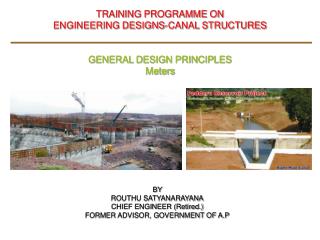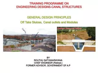
TRAINING PROGRAMME ON ENGINEERING DESIGNS-CANAL STRUCTURES GENERAL DESIGN PRINCIPLES CANALS
660 likes | 1.56k Views
TRAINING PROGRAMME ON ENGINEERING DESIGNS-CANAL STRUCTURES GENERAL DESIGN PRINCIPLES CANALS. BY ROUTHU SATYANARAYANA CHIEF ENGINEER (Retired.) FORMER ADVISOR, GOVERNMENT OF A.P. Canal & Design Principles. Introduction:

TRAINING PROGRAMME ON ENGINEERING DESIGNS-CANAL STRUCTURES GENERAL DESIGN PRINCIPLES CANALS
E N D
Presentation Transcript
TRAINING PROGRAMME ON ENGINEERING DESIGNS-CANAL STRUCTURES GENERAL DESIGN PRINCIPLES CANALS BY ROUTHU SATYANARAYANACHIEF ENGINEER (Retired.)FORMER ADVISOR, GOVERNMENT OF A.P
Canal & Design Principles • Introduction: • Irrigation is the process of artificially supplying water to soil for raising crops. It is a science of planning and designing an efficient, low cost, economic irrigation system tailored to fit natural conditions. • It includes the study and design of works in connection with river control, drainage, and hydraulic power generation. • The source of water for irrigation is precipitation. • Artificial irrigation can be divided into lift irrigation and flow irrigation. • Irrigation schemes consist of storage or diversion structures and canal distribution system.
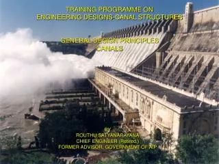
Canal & Design Principles • Introduction: • The NagarjunaSagar Scheme (NSS) is a multipurpose project, comprising a dam across the river Krishna and two main canals, one on either flank of the river. Besides providing irrigation water supplies to 8, 95,547 ha of parched lands. • It is the largest and highest stone masonry dam in the world. • The construction of the dam was commenced in 1957 and completed by 1970. • Erection of Spillway radial gates was completed during 1973-74. • The dam comprises 1450m long gravity masonry dam flanked by 2560m long earth dam on the left side and 853m long earth dam on the right side. • The maximum height of the main dam above the deepest bed level of +59.74m is 124.66m. The top of the dam is +184.40m in masonry dam and +185.93m in earth dam portions. • The Spillway is 471m long with crest level at +166.420m and top of the 26 numbers of radial crest gates of size 13.72m x 13.41m each is at +179.83m.The Spillway can tackle a maximum flood discharge of 45,306 cumec (1.60 million cusec).
Canal & Design Principles • Introduction: • Nagarjunasagar canal system: • The NagarjunaSagar Canal System is one of the largest in India. • Two canals run on contour, take off from each flank. ____________________________________________________________________ Detail Jawahar canal Lalbahadur canal ____________________________________________________________________ 1. Command area in Hectares 4 75 304 Ha. 4 20 243 Ha. 2. Length in Kilometers (Kms.) 203 297 including 117 long 21st Branch 3. Branch canals in Kms 269 (9 nos) 198 4. Distributaries in Kms 5342 7722 5. Field Channels in Kms 14 400 9654 6. No. os blocks 22 21 + 11 7. Water allocation 132 TMC 132 TMC 8. Water release 4th August, 1967 Smt. Indira Gandhi, PM ____________________________________________________________________
Canal & Design Principles • Introduction: • Existing deficiencies in the Canal system • The canal system is in a damaged condition due to insufficient maintenance over the past several years. • The distribution system, particularly, is in a bad shape, and have lost their designed carrying capacity. • Several structures and canal lining have been damaged. • The shutters of the OTs are either inoperable or not available. • Extensive growth of vegetation and plants inside the canal prism. • It is impossible to approach the system for inspection and maintenance. • There have been recurrent breaches and slips in several vulnerable embankment reaches. • The deep cut reaches have suffered extensive damages due to slope slips/rock falls, collapsed lining etc. • The net result of these deficiencies is that there is significant reduction in the irrigated area in the command area.
Canal & Design Principles • Introduction: • The Government of Andhra Pradesh has taken up Rehabilitation and Modernization of Nagarjunasagar Scheme under Andhra Pradesh Water Sector Improvement Project (APWSIP) with the World Bank Financial Assistance. • The APWSIP has the following four components: (i). Component A: Improving irrigation service delivery and management (ii). Component B: Irrigated agriculture intensification and diversification: (iii). Component C: Water sector institutional restructuring and capacity building: (iv). Component D: Project Management: • Component A • The following two sub components are part of the component - A (i). Sub- component A-1: Participatory rehabilitation and modernization of Irrigation system. (ii). Sub- component A-2: Dam safety works.
Canal & Design Principles • Introduction: (A). The rehabilitation works will comprise the following: • Removal of silt, vegetation, bushes and plants within the canal prism and bank • Resectioning of canals and strengthening of banks, • Resectioning of canal banks to bring the top width of banks to acceptable design standards, • Treatment of sub-grade with cohesive non-swelling soils in the reaches associated with swelling black cotton soils, • Mechanized placement of CC lining in vulnerable canal reaches and providing protective CC lining on upstream and downstream of canal structures, • Repairs/ replacement of damaged canal structures. • Repairs/replacement of damaged / non-functional mechanical and electrical fixtures, gates and equipment. • Remodeling of majors and minors to original designs standards and providing CC lining, • Implementation of remedial measures in the deep cut reaches of main canals, • Providing additional cross regulators in the 21st main branch canal, • Improvement of inspection roads on canal banks, ( cont….)
Canal & Design Principles • Introduction: (B). The modernization works will comprise the following: • Construction of measuring devices in main canals, branch canals, majors, and in the entire distribution system (minors/ sub – minors), • Providing proportional distributor structures for designed flow of water into the minor/sub-minor without gates and installation of APM outlets, • Introducing motorized operation of gates to the optimum possible extent on important structures,
Canal & Design Principles • Introduction: (C). Lift Irrigation Schemes • Repairs will be carried out to the civil work and electro- mechanical equipment including replacement of some pumping equipment of the existing lift irrigation schemes on Jawahar Canal and Lal Bahadur Canal. (D). Supplementation Schemes • It is proposed to utilize the seepage/regenerated water in the command area for supplying to the tail end areas in the gap ayacut through construction of suitable diversion schemes. Consultancy: • M/S SMEC International Pty Limited, Australia in association with M/S SMEC (India) Pvt. Limited, Gurgaon have been appointed by Government of Andhra Pradesh as Consultants for Engineering Design for Rehabilitation and Modernization of NSS under APWSIP.
Canal & Design Principles • Introduction: • Consultancy: • The main tasks and activities are as follows: (i). To chalk out the programme for preparation of design/drawings and construction drawings in consultation with CE, NSP. (ii). To review the original design parameters (hydraulic and structural) adopted for canals and canal structures (main canals, branch canals, major and minor distributaries) and to provide revised design/drawings, ensuring that the original designed canal capacities for the canal network is maintained. (iii). To prepare the design/drawings for the new structures, wherever required and for the damaged structures requiring large scale modification in the structural designs based on the field and other relevant data supplied by the Department and also to prepare construction drawings for these structures, in accordance with relevant IS Codes. (iv). To prepare package wise construction drawings for canals and canal structures, which are included in the Rehabilitation and Modernization packages of canal system and Dam Safety Works packages. (Cont….)
Canal & Design Principles • Introduction: • Consultancy: • The main tasks and activities are as follows: (v). To prepare design/drawings for dam safety works based on the recommendations of Dam Safety Review Panel (DSRP) in consultation with C E, NSP and CE, C. D. O. (vi). To prepare type designs of canal sections and canal structures to each hydraulic reach of distributary system to suit different sub-grade conditions. (vii). To prepare design of hydro-mechanical works and to check designs/ drawings and specifications submitted by manufactures/ contractors for hydro- mechanical works. (viii) .To impart training to the APWSIP personnel, based on the training programme to be structured in consultation with the Department.* (ix). To computerize all design/drawings and relevant data for record and further reference and to keep the record of hard copies of design/drawings.
Canal & Design Principles • Introduction: • The canal structures can be divided into the following categories based on their functional requirement. (i). Cross drainage structures (ii). Control structures (iii). Communication or service structures (iv). Flow measurement structures
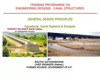
Cross Drainage (CD) & Cross Masonry Works • Definition: • Works which are constructed at the crossing of natural drain or stream or a canal, so as to dispose of the drainage water without interruption of canal supplies are known as Cross Drainage (CD) works. • Structures Carrying canal over Natural Drains: • Aqueducts, • Under Tunnels (UTs), • Syphons Aqueducts, • Culverts and Bridges, • Inlets & Outlets. (cont…)
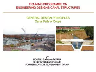
Cross Drainage (CD) & Cross Masonry Works • Definition: • Works which are constructed to control and regulate the discharges, depths, velocities etc, to ensure efficient function of the Canal system are known as canal regulation works or Cross Masonry (CM) works. • Control Structures: • Head Regulators, • Cross Regulators, • Sluices, • Escapes, • Canal Falls or drops,, • Canal Outlets and Modules, • Silt Ejectors. (cont…..)
Cross Drainage (CD) & Cross Masonry Works • Definition: • Communication and Service Structures: • Culverts and Bridges. • Flow Measurement Structures or Meters: • Metering Flumes and • Weirs • Drops or falls.
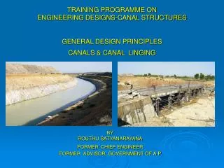
Canal & Design Principles • Definition: • A canal is an artificial channel, trapezoidal in shape to carry water to the field from a source, such as a reservoir, river or a tank. • The motive force in the flow of an open channel is the slope of the water surface • The water flows from higher level to lower level by virtue of gravity. • The resistance in the canal are surface tension, atmospheric pressure, surface friction at the bottom and sides.
Canal & Design Principles • Canal Alignment: • The canal has to be aligned in such a way that it covers the entire area proposed to be irrigated with the shortest possible length and at the same time its cost includes the cost of Cross Drainage and Cross Masonry works and they are the minimum. • A shorter length ensures less loss of head due to friction and smaller loss of discharge due to seepage and evaporation.
Canals & Design Principles • Classification: Canals are classified based on • Canal excavation in Soils: Alluvial Canals and Non- alluvial Canals • Functions of the Canal: Irrigation Canal–Carrier Canal Feeder canal – Navigation Canal – Power Canal • Shape of channel: Circular, Rectangular, Trapezoidal, Triangular, Parabolic • Canal alignment: Contour Canals - Ridge Canals or water shed canals – Side Slope Canals. • Discharge and Importance: Main Canal-Branch Canal-Major and Minor Distributaries-Water course. • Nature of the Canal: Un-lined canal-Lined canal.
Canals & Design Principles • Design parameters: • Definitions: • Water requirement of a crop: • Total quantity of water required from the time of sown to it is harvested. • Crop Period: • It is the time, in days required for irrigated water from sowing to last wetting. • Base Period (B): • The period for which water is supplied in days from ground preparation for planting to the last wetting. • Duty of water or Duty (D): • It is the irrigation capacity of unit water, expressed in Hectares per Cumecs (acres per cusec). • Delta Δ : • It is the total depth of water required to a crop for its full growth may be expressed in hectare-meters (Acre-ft), in million cubic meters (million cubic feet) or simply as depth of water (without percolation or evaporation loses).
Canals & Design Principles • Design Parameters: • Duty of water or Duty (D): • It can be expressed as, • 1. One cumec of water can irrigate the number of Hectares during base period. i.e. 1700 hectares/cumec (120 acres /cusec) • 2. Total depth of water (delta) i.e. 1200mm (4 feet) over a base period. • 3. One million cubic meters can irrigate number of Hectares.Being adopted in minor irrigation Tanks (10000 acres per TMC) • 4. Hectare meters water can irrigate number of hectares i, being adopted for tanks. • CROPS AND CROP CALANDER: • After deciding the cropping pattern water requirement of each crop shall be worked out considering the soil conditions and the climatic conditions by a suitable method like modified penman’s method
Canals & Design Principles • Design parameters: • Definitions: • Relation ship between Delta and Duty: Volume (V) in B days = (60x60x24xB) = 86 400 B Cubic meters or cubic feet • Δ. Depth of water = Volume/Area =86 400/104D = 8.64 B/D in meters or 864 B/D cm. in MKS System or 86 400 B/43 560D= 1.985B/D or Say 2.00 B/D in FPS System • D. Duty = 8.64/Δ in Hectors/ cumecs in MKS System or 1.985B/Δ or say 2 B/Δ in acres / cusec in FPS system 1 Acre = 0.4047 hectare 1 hectare = 104 Sq.m or 2.471 acres. 1 c/s = 0.0283 cumecs 1 acre per c/s = 14.3 hectare/cumec 1 day = 24x60x60 = 86 400 seconds 1 cumec day = 8.64 hectare meters or 86 400 cubic meters 1 cusec of water running for a day = 2 acre feet. 1 acre ft. = 43 560 cu.ft.
Canals & Design Principles • Design parameters: Duty in NSP at head including losses; ______________________________________________________________________________ Sl. No Irrigated Area in ha. ID in ha/cum Wet in ha/cum ID CUM Wet in ha/cum ______________________________________________________________________________ 1. >12 000 850 715 850 >4 000 up to 12 000 900 760 925 3. >40 up to 4 000 1000 800 1000 4. Up to 40 at pipe outlet 1400 850 1075 ______________________________________________________________________________
Canals & Design Principles • Design parameters: Value of Delta in India ______________________________________________________________________________ Sl. No Crop Base period in days Delta in field in Hectare/cumec _____________________________________________________________________________ 1. Rice 120 900 2. Wheat 120 1800 3. Sugar cane 360 800 4. Cotton 200 1400 5. Vegetables 120 700 6. Bajri 120 500 7. Ground –nut 8. Chilies ______________________________________________________________________________
Canals & Design Principles • Design parameters: • Discharge: • The discharge capacity of the canal is the maximum discharge required for the ayacut for the given duty and the losses in the system. • It shall be fixed based on, • The cultivable command area, • Water allowance, i.e. the outlet capacity in cumecs/s per thousand hectares considering the duty, intensity, proposed crop ratio, water availability, etc; and • Transmission losses due to seepage and evaporation from canals water courses and irrigated area.
Canals & Design Principles • Design parameters: • Discharge: • The carrying capacities of the canals and distributaries have to be worked out from head to tail. • The canal and the distributaries shall be designed not only to carry the supplies at peak demand but also to carry the normal supplies at all times, with water levels sufficient to irrigate the command. • Full Supply Level (FSL): • The levels of water required in a channel are the levels that command the land in full, or the maximum water level available at the source. • The FSLs shall be decided beginning with out lets, minors, distributaries, branch canals, and then main canal. • The design of canals and distributaries to be carried out such that the command of all lands is attained even when half of full supplies are carried.
Canals & Design Principles • Design parameters: • Best Discharging Channel is that which for the same Cross Section and slope, passes water with the maximum velocity and the maximum hydraulic mean radius (R=A/P), and with the smallest absorption losses commensurate with economy. • The canal has to be aligned in such a way that it covers the entire area proposed to be irrigated with the shortest possible length and at the same time its cost includes the cost of Cross Drainage and Cross Masonry works and they are the minimum.
Canals & Design Principles • Design parameters: • The common procedure is to determine the Width (W) and Depth (D) of a canal for a given discharge (Q), coefficient of rugosity, side slopes, surface fall or bed gradient, and minimum and maximum velocity. The formula for determine the discharge capacity of the canal. Discharge (Q) = A (area ) x V ( Velocity) • The Cross section of the canal will be in • Full cutting • Full banking or • Partial cutting and Partial banking
Canals & Design Principles • Important Guidelines: • Alignment: • As for as possible Avoid: • CM &CD works on curves. • Canal Syphons • Flume sections • Inlets and out lets • Skew crossings of Bridges and CM & CD works • Provide bridges at designated roads without foregoing the available facility. • Sluices – Discharge conditions: • Distributaries to draw Full supply when the parent canal is running at three fourths (3/4th) discharge at the head reach or up to the parent canal decreases to 20% of full discharge at head. • Distributaries to draw full supply when the parent canal is running at Half supply(1/2) discharge at the tail end reaches, or where the parent canal discharge is reduced to 20% of the full discharge at the head.
Canals & Design Principles • Important Guidelines: • Alignment: • Recommended Loss of head at structures: ______________________________________________ CM&CD works Head loss in mm ______________________________________________ Cross Regulator 75 to 150 Aqueduct 75 to 150 Canal Syphon 75 to 150 Measuring device 75 Bridges Not permitted ______________________________________________
Canals & Design Principles • Important Guidelines: • Statements: • HP (Hydraulic Particulars) statements reach wise with discharge calculations. • Design of cross sections reach wise. • Reach wise ayacut statement. • Statement of Structures with HPs reach wise • Curves statement • Statement of culverts and Bridges • Statement of Regulators • Statement of OTs • Statement of drops • Statement of canal/surplus escapes • Statement of CD works • Statement of CM works. • Recommended Loss of head at structures:
Canals & Design Principles • Important Guidelines: • Plans and Drawings: • LS (Longitudinal section) together with site plan with contos showing TBL/FSL/CBL GL, reach wise CSs, HPs reach wise, TP particulars, command boundaries survey numbers wise and, Village wise. • Design of cross sections reach wise. • Condensed LS Reach wise. • Index plan showing the head works and canal alignment with alternatives studied, and duly marking the final alignment.