Download
1 / 12
120 likes | 138 Views
Explore the designs for 500 GeV and 3 TeV CM, detailing lengths, angles at IPs, optics, and collimation for optimal beam dynamics. Upgrade from 250 GeV to 500 GeV layout while maintaining key features. Constraints and considerations for efficient operation are discussed.

E N D
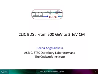
CLIC BDS : From 500 GeV to 3 TeV CM Deepa Angal-Kalinin ASTeC, STFC Daresbury Laboratory and The Cockcroft Institute
Layout for 500 GeV and 3 TeV CM designs 0 -1 3 TeV CM Total length : 2795.93 m Angle at the IP : -0.601 mrad Horizontal offset at IP : -1.5702 m -2 -3 -4 0 500 1000 1500 2000 2500 0 Location of IP fixed. Post collision lines and 14 MW beam dump location same. -1 500 GeV CM Total length : 1727.63 m Angle at the IP : -1.598 mrad Horizontal offset at IP : -3.6049 m -2 -3 -4 0 500 1000 1500
Optics of 1.5 TeV BDS Betatron Collimation Final Focus Diagnostics Energy Collimation Lengths of dipoles : ECOL : B3A , B3B, B4A, B4B = 11.302083 m FFS : B1,B2 :1.490472m, B3 = 7.328154 m, B4 =2.7140265 m
Optics of 250 GeV BDS Betatron Collimation Energy Collimation Final Focus Diagnostics Shorter beam delivery system design at 500 GeV CM. Design optimised from beam dynamics point of view : beam spot at energy spoiler & better control of aberrations Lengths of dipoles : ECOL : B3A, B3B, B4A, B4B = 5.6510417 m FFS : B1 :1.8288m, B2=1.8288m, B3 = 8.9916 m, B4 =2.10312m
ILC collimation + FFS : upgrade from 250 GeV to 500 GeV Decimated dipoles, reserved space for additional dipoles. Keep the layout fixed. Quadrupoles & Sextupoles unchanged. Need to change FD 250 GeV 500 GeV
ILC muon shield in a tunnel vault ILC (RDR, volume II)
CLIC BDS : Dipole fields at 1.5 TeV Dipole fields (Gauss) S(m) Fields factor of 6 lower at 250 GeV, need to decimate dipoles
Upstream Polarimeter P. Schüler, CLIC08 Longitudinal position along BDS(m) • For Physics requirements, upstream polarimetry needs to be robust and fast and need to provide ΔP/P = 0.25%. • Need directional tolerance between Compton IP and IR to be < 13 mrad • Location at s=742 m is aligned within 3.8 mradw.r.t. IP, has 20 m space for laser beam crossing and is upstream of energy collimation which is desirable. Angular deflection (mrad) S=742 m Xp=-605.135 mrad IP Xp=-605.351 mrad The location of polarimetry in the 250 GeV lattice – different due to different net angle at the IP and shorter energy collimation. Perhaps a dedicated chicane like in the ILC plausible at 250 GeV?
Upstream Energy Measurements No dedicated chicane like in ILC due to Space constraints. Possible to measure energy using First dipole in the energy collimation section with resolution of 0.04%. Conceptual layout. Needs to be included in the lattice by adjusting the fields of first dipoles to provide the required drift space. Should not affect the optics severely. May be possible to include a chicane at 500 GeV CM if different layout is acceptable?
Define layout constraints • Location of IP, post collimation lines and dump locations same • Angle at the IP same. • Is it absolutely essential to have a shorter BDS (the length difference is 1068m on single BDS)? • Tunnel constraints • Experimental hall + Main dump shafts (stay same) • Muon wall tunnel vault locations should stay same • Locations for other shafts, caverns should be compatible for both the layouts • Diagnostics section : LW set up, polarimetry and spectrometry • Collimators • Crab system • Collective effects • Vacuum pipe radius • ……………?
Lattice constraints • Beam spot size at laser wires in the beam diagnostics section • Beam spot size at energy spoiler • Betatron collimation : phase advances w.r.t. IP/FD, collimation depths, gaps, efficiency, wake fields, background (including muons) • Upstream polarimetry & spectrometry • IP parameters : bx, by, n, nx’ & luminosity • Maximum pole tip fields in quadrupoles and sextupoles (length and apertures) • Minimum dipole fields • Synchrotron radiation • Final doublet • Post collision line (is there a 500 GeV lattice?)