Download
1 / 11
110 likes | 184 Views
Directed Bonding Models: Lewis Dot and VSEPR. Lewis Dot Structures Use dots to represent valence electrons. Pairs of dots (lines) between atoms are bonds (multiple pairs of dots represent multiple bonds). Valence electrons not involved in bonds are usually in pairs.

E N D
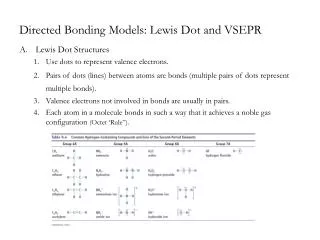
Directed Bonding Models: Lewis Dot and VSEPR • Lewis Dot Structures • Use dots to represent valence electrons. • Pairs of dots (lines) between atoms are bonds (multiple pairs of dots represent multiple bonds). • Valence electrons not involved in bonds are usually in pairs. • Each atom in a molecule bonds in such a way that it achieves a noble gas configuration (Octet ‘Rule”).
Writing Lewis Dot Structures • Determine number of valence electrons in molecule • cations (+) subtract electrons • anions (-) add electrons • Write skeleton structure for molecule • least electronegative element at the center • use formula a hint • H’s always, and Halides most often, terminal (NEVER form multiple bonds) • oxygens do not like to bond together (with a few exceptions) • oxygens most often have at least two sets of nonbonding pairs • Subtract 2 electrons for each bond in skeleton structure • Subtract 2 electrons for each lone pair added to structure • Distribute remaining valence electrons so that all atoms have complete octet • may need to introduce multiple bonds
SO3 Writing Lewis Dot Structures: Example O S O O
Exceptions to the Octet Rule • Elements of group IIIA form “electron deficient” compounds; have incomplete octet. BF3 • Elements with Z > 14 may have “expended octets” (10 or 12 electrons).
Formal Charges • :O: • :O N OH • simple means of bookkeeping • the + and - signs do not necessarily indicate actual charges • negative charge on more electronegative atom • sum of Formal Charges = charge on molecule or ion • Electroneutrality principle: formal Charges are to be avoided whenever possible • e.g. draw 2 structures for CHN, which actually exists? • H C N: H N C: F.C. = valence electrons - nonbonding electrons - bonds .. .. .. .. N = 5 - 0 - 4 = +1 O = 6 - 6- 1 = -1 + +
Resonance • in many cases there are multiple equivalent places to put multiple bonds: • O O • e.g. HNO3 O N OH O N OH • note: all N-O bond lengths are identical; but neither single nor double. • if 2 or more Lewis structures exist using the same backbone, then resonance is said to exist • the individual structures = contributing structures • the molecule itself is a resonance hybrid of the contributing structures • represent hybrid by drawing contributing structures and separating them by a • the resonance hybrid is a blend (average) of the contributing structures O • O N OH - - + + - bond lengths equivalent to a 11/2bond +
Molecular Shape • Valence Shell Electron Pair Repulsion Model (VSEPR) • Most Important Rule #1: • The bond angles around a central atom are those which maximize the distance between electron pairs in the valence shell of the atom • Procedure: • Draw Lewis structure • Count the number of electron pairs (both bonding and non-bonding) • multiple bonds as single “pair” • Determine Ideal Molecular Geometry • Make Corrections to Ideal Geometry • Nomenclature: • electronic geometry: how all electron pairs (bonding and non-bonding) are arranged about the central atom • molecular geometry: how all bonding pairs are arranged about that central atom
Electron Pair Geometry Ideal Molecular Geometry Electron Pairs Angle(s) Name Two (sp) 180o linear Three (sp2 ) 120o trigonal planar Four (sp3) 109.5o tetrahedral Five (sp3d) 120o & 90o trigonal bipyramidal Six (sp3d2) 180o octahedral
Corrections to Ideal Molecular Geometry • Nonbonding Domains • nonbonding domains occupy more space than bonding domains • don’t “see” nonbonding domains, but do see their effects • repulsions: NBD-NBD > NBD-BD > BD-BD correction: H-N-H bond angle less than ideal ideal geometry: trigonal pyramidal electronic geometry: tetrahedral
Corrections to Ideal Molecular Geometry • Multiple Bonds • “count” as 1 bonding pair • larger than single bonds; take up more room • :O::O: • C C • Cl Cl Cl Cl • Electronegative Substituents bonding pairs to electronegative substituents occupy less space that those to more electropositive substituents. ideal geometry: trigonal planar correction: Cl-C-Cl bond angle less than ideal ●● P X X X X Θ F 97.8 Cl 100.3 Br 101.5 I 102 electronegativity Θ