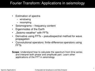
MEMS Applications in Seismology
MEMS Applications in Seismology. Nov 11, 2009 Seismic Instrumentation Technology Symposium B. John Merchant Technical Staff Sandia National Laboratories.

MEMS Applications in Seismology
E N D
Presentation Transcript
MEMS ApplicationsinSeismology Nov 11, 2009 Seismic Instrumentation Technology Symposium B. John Merchant Technical Staff Sandia National Laboratories Sandia is a multiprogram laboratory operated by Sandia Corporation, a Lockheed Martin Company,for the United States Department of Energy’s National Nuclear Security Administration under contract DE-AC04-94AL85000.
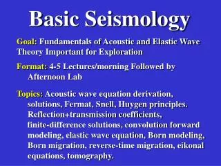
Outline • Overview of MEMS Technology • MEMS Accelerometers • Seismic Requirements • Commercial Availability • Noise & Detection Theory • Current R & D Efforts • Outlook
Courtesy of Sandia National Laboratories, SUMMiTTM Technologies, www.mems.sandia.gov What are MEMS? Micro-Electro-Mechanical Systems (MEMS) Features range from 1 to 100 microns. Similar fabrication techniques as Integrated Circuits (IC). However, MEMS fabrication is a trickier process due to the incorporation of mechanical features Distinguished from traditional mechanical systems more by their materials and methods of fabrication than by feature size.
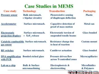
Surface Micromachining Bulk Micromachining LIGA Structures formed by deposition and etching of sacrificial and structural thin films Structures formed by wet and/or dry etching of silicon substrate Structures formed by mold fabrication, followed by injection molding Silicon Substrate Groove Nozzle Membrane p++ (B) Wet Etch Patterns Poly Si Silicon Substrate Holes Channels Metal Mold Silicon Substrate Dry Etch Patterns Three Dominant MEMS Microfabrication Technologies Courtesy of SNL MEMS Technology short course
MEMS History 1989 – Lateral Comb drive at Sandia National Laboratories 1970’s - IBM develops a micro-machined pressure sensor used in blood pressure cuffs Decreasing Costs Increasing Commercialization 1986 – LIGA process for X-ray lithography enable more refined structures 1991 – Analog Devices develops the first commercial MEMS accelerometer for air bag deployment (ADXL50) 1994 – Deep Reactive-Ion Etching (DRIE) process developed by Bosch. 1979 - HP develops inkjet cartridges using micro-machined nozzles 1988 – first rotary electro-static drive motors developed at UC Berkley 1993 – Texas Instruments begins selling DLP Projectors with Digital Mirrors.
Micromirror switch Lucent Technologies Ink Jet Cartridge Hewlett Packard MEMS Commercial Applications Digital Mirror Device Texas Instruments Accelerometer Analog Devices Pressure Sensor Bosch MEMS Courtesy of SNL MEMS Technology short course
MEMS Accelerometer History 2002 – Applied MEMS (now Colibrys) releases low-noise Si-Flex Accelerometer: +/- 3 g Peak 300 ng/√Hz Noise • 1991 – Air Bag Sensor Analog Devices (ADXL50) • +/- 50 g Peak • 6.6 mg/√Hz Noise 2006 – Nintendo Wii Controller (Analog Devices ADXL330). +/- 3 g Peak 350 ug/√Hz Noise 2004 – Colibrys VectorSeis Digital 3 Channel Accelerometer 2 – 1000 Hz +/- 0.335 g Peak ~50 ng/√Hz Noise 2005 – Sercel 428XL-DSU3 2 – 800 Hz +/- 0.5 g Peak ~40 ng/√Hz Noise
What makes a MEMS Seismometer A MEMS Accelerometer with: • Low noise floor (ng’s/√Hz) • ~1 g upper range • High sensitivity Modeled as a spring-mass system Proof mass measured in milli-grams Bandwidth below the springs resonant mode (noise and response flat to acceleration)
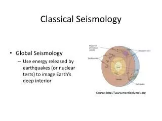
Seismology Requirements • Noise floor (relative to the LNM) • Peak acceleration (Strong vs weak motion) • Sensitivity • Linear dynamic range • Bandwidth (short-period, long-period, broadband) High Noise Model Low Noise Model Current Best MEMS SP Target Region GS13 KS54000 Requirements are ultimately application dependent
Strong Motion Requirements Many of the strong motion requirements may be met by today’s MEMS Acclerometers:
Weak Motion Requirements Weak motion requirements are more demanding: There are no MEMS accelerometers available today that meet the weak motion requirements.
Commercially Availability There are many manufacturer’s of MEMS Accelerometers. Most are targeted towards consumer, automotive, and industrial applications. Only a few approach the noise levels necessary for strong-motion seismic applications Manufacturers Analog Devices Bosch-Sensortec *Colibrys *Endevco Freescale *GeoSIG *Kinemetrics Kionix MEMSIC *PCB *Reftek Silicon Designs STMicroelectronics Summit Instruments *Sercel *Wilcoxon *Noise Floor < 1 ug/√Hz
Colibrys Formerly Applied MEMS, I/O. Oil & Gas Exploration Produces VectorSeis which is sold through ION (www.iongeo.com) *discontinued
Endevco, PCB, Wilcoxon Not strictly MEMS, but they are small and relatively low-noise. All three companies make fairly similar Piezoelectric accelerometers Industrial and Structural applications
Kinemetrics Strong motion, seismic measurement Force Balance Accelerometer Available in single and three axis configurations
Reftek Strong motion measurement for seismic, structural, industrial monitoring Available in single, three axis, and borehole configurations * uses Colibrys Accelerometers
Sercel Used in tomography studies for Oil & Gas Exploration Sold as complete turn-key systems and not available for individual sales
MEMS accelerometers Advantages • Small • Can be low power, for less sensitive sensors. • High frequency bandwidth (~ 1 kHz) Disadvantages • Active device, requires power • Poor noise and response at low frequencies (< 1 Hz), largely due to small mass, 1/f noise, or feedback control corner. • Noise floor flat to acceleration, exacerbates noise issues at low frequency (< 1 Hz)
Boltzman’s Constant kB=1.38x10⁻²³ J/K Temperature T = 300 K Resonant Frequency wo=314.16 rad/s (50Hz) Quality Factor Q = 1000 Proof Mass m = 1 gram (10-3 kg) an = 2.3 x 10^-9 m / s2 / √Hz = 0.2ng / √Hz Theoretical Noise Thermo-mechanical noise for a cantilevered spring Two main sources of noise: • Thermo-mechanical • Brownian motion • Spring imperfections • Electronic • Electronics • Detection of mass position • Noise characteristics unique to detection technique
Detection of mass position Variety of ways to determine mass-position • Piezoelectric / Piezoresistive • Capacitive • Inductive • Magnetic • Fluidic • Optical (diffraction, fabry-perot, michelson)
Capacitive Detection The most common method of mass position detection for current MEMS accelerometers is capacitive. Capacitance is a weak sensing mechanism and force (for feedback contrl) which necessitates small masses (milligrams) and small distances (microns). Feedback control employed for quietest solutions. Differential sampling for noise cancelation. Colibrys bulk-micromachined proof mass sandwiched between differential capacitive plates Silicon Designs capacitive plate with a pedestal and torsion bar.
R&D Challenges • Large proof mass and weak springs required. This makes for a delicate instrument. • Capacitance less useful as a detection and feedback mechanism for larger masses. • Feedback control required to achieve desired dynamic range and sensitivity. • R&D requires access to expensive MEMS fabrication facility • 1/f electronic noise could limit low-frequency
DOE Funded R&D Projects • Several posters on display • Additional details and proceedings available athttp://www.monitoringresearchreview.com/ • Characteristics: • Significantly larger proof mass (0.25 – 2 grams) • Non-capacitive mass position sensing (inductive, optical, fluidic) • Feedback control
DOE Funded R&D Projects Kinemetrics / Imperial College • Inductive coil with force feedback • Proof mass of 0.245 grams • 0.1 - 40 Hz bandwidth, resonant mode at 11.5 Hz • Demonstrated noise performance of 2-3 ng/√Hz over 0.04 – 0.1 Hz, higher noise at frequencies > 0.1 Hz • Symphony Acoustics • Fabry-Perot optical cavity • Proof mass of 1 gram • 0.1 - 100Hz bandwidth • Demonstrated noise performance of 10 ng/√Hz • Theoretical noise performance of 0.5 ng/√Hz
DOE Funded R&D Projects Photo Diodes Reflective Surface Folded Springs Sandia National Laboratories • Large proof mass (1 gram, tungsten) • Meso-scale proof mass with MEMS diffraction grating and springs. • Optical diffraction grating • Theoretical thermo-mechanical noise 0.2 ng/√Hz over 0.1 to 40 Hz Optical Grating Proof Mass Frame Proof Mass Fixed Frame • Silicon Audio • Large proof mass (2 gram) • Meso-scale construction with MEMS diffraction grating • Optical diffraction grating • 0.1 to 100 Hz target bandwidth • Theoretical thermo-mechanical noise 0.5 ng/√Hz over 1 to 100 Hz
DOE Funded R&D Projects • PMD Scientific, Inc. • Electrochemical fluid passing through a membrane • Theoretical noise 0.5 ng/√Hz over 0.02 to 16 Hz • Michigan Aerospace Corp. • Whispering Gallery Seismometer • Optical coupling between a strained dielectric microsphere and an optical fiber • Theoretical noise of 10 ng/√Hz
5 year outlook • Over the next 5 years, there is a strong potential for at least one of the DOE R&D MEMS Seismometer projects to reach the point of commercialization. • This would mean a MEMS Accelerometer with: • a noise floor under the < LNM (~ 0.4 ng/√Hz) • Bandwidth between 0.1 and 100 Hz, • > 120 dB of dynamic range • small ( < 1 inch^3). • Low power (10’s mW)
Enabling Applications • Flexible R&D deployments • Why simply connect a miniaturized transducer onto a traditional seismic system? • Will require highly integrated packages: • Digitizer • Microcontroller • GPS • Flash storage • Communications • Battery Power Source Antenna Battery Backup Radio / Ethernet orientation • Storage • Waveforms • Parameters • Detection templates • Microprocessor • Data Retrieval • Algorithms • Communications Compass GPS location, time waveform time series 3-axis Accelerometer
10 year outlook • MEMS Accelerometers have only been commercially available for ~18 years. • Where were things 10 years ago? • Further expansion into long period (~ 0.01 Hz) • Small, highly integrated seismic systems