Download
1 / 15
150 likes | 271 Views
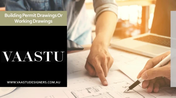
Building Drawings. Standard Grade Graphic Communications. Introduction.

E N D
Building Drawings Standard Grade Graphic Communications
Introduction • A building or construction project requires a complete set of specialised drawings. These drawings, called a project set, are used by the local planning department and building control, as well as by builders, joiners, plumbers, electricians and water, gas and telephone engineers. • The buildings are designed by an architect with a team of technicians and surveyors to help plan and produce the drawings. The types of drawings are designed by an architect with a team of technicians and surveyors to help plan and produce the drawing. • The types of drawings you need to know about are: • location plans • site (block) plans • floor plan • Drawings for new buildings require approval from the building control department and the planning department before construction work can begin. The building control department checks that the quality of design and construction meet British standards. The planning department assesses whether or not the style and proportions of the proposed building are appropriate for the location.
Location Plan • It identifies the location of the proposed new building within its surroundings. It also helps the builder to plan the layout of a new building scheme and is required by the local government planning department which decided whether or not to approve the project. • Neighbouring buildings and their boundaries are shown, as are roads, street names and fields. • The scale of the drawing depends on the size of the whole building scheme but is normally 1:1250 • All building projects come under local authority control .
Site (Block) Plan • A site plan (also known as a block plan) shows the site boundary and the outline of the new building which are highlighted in the location plan. • Paths, roads and neighbouring plots are also shown. This type of plan enables the builder to mark out the site, lay drainage pipes and build manholes. • It is also submitted to the local planning department for approval. • A site plan can show: • existing trees • the building outline, including the roof • the main dimensions of the house and site and metres • drainage pipes and manholes which run from the bathroom and kitchen to the main drain under the road • the position of the house on the site • contour lines which show the slope of the land The scale of a site plan depends on the size of the building. For houses and small buildings a 1:200 scale is used.
Location Plan showing: Neighbouring buildings boundaries Roads Street names House/plot numbers Fields and Direction arrow indicating North Site Plan showing: Site boundary Building outline Neighbouring paths, roads and plots Existing trees Homework - Location Plans and Site Plans Sketch the following building drawings
Floor Plan • A floor plan is a type of sectional view of the building with the roof and a few layers of bricks removed to show: • the arrangement of rooms • the positions of windows and doors • the types of internal and external Floor plans are used by builders, plumbers, electricians and joiners to help plan the construction work and to cost the building materials. The scale of a floor plan depends on the size of the building but for most domestic buildings a sale of 1:50 is used Floor plan can also include: the dimensions of each room & the exact positions of doors & windows the layout of water pipes (plumbing) the layout of electrical cabling and positions of sockets, switches and fuse boxes
Fixtures, Appliances and Symbols • More detailed floor plans show the layout of kitchens and bathrooms, since these are rooms which have fixtures and appliances. BSI symbols are used to simplify the drawing of common features. Sink Window Lamp Door Switch Washbasin Radiator Socket Shower tray In-line valve Insulation Brickwork Bath Crossover Concrete Sawn wood Sink top Junctions
Task – Floor Plans and Sectional Views • Produce an accurate floor plan of a room in your home using the correct symbols learnt in this section. • Duration: 20mins • Should you wish you may re-visit your kitchen floor plan and improve.
End of Lesson 1 Building Drawings
Sectional View • A cross-section showing a slice through the wall gives builders, joiners and roofers a great deal of information about how the house should be built, • Sections can be shown through any part of the building and normally a scale of 1:20 is used. The local building control department needs sectional views and floor plans to assess the quality of construction design.
Elevations • Elevations are orthographic projections of a building produced by its architect or designer. • Elevations are required by the local planning department to assess whether the style and proportions of the proposed building are appropriate for the location. Builders also need a picture of what the house will look like from the outside.
Schematic Diagrams • Heating engineers, plumbers and electricians work from schematic diagrams. The purpose of a schematic diagram is to present a complex 3-D installation in a simple 2-D form. Symbols are used to represent common parts such as radiators, valves and water tanks. • The 3-D layout shown is complicated and time-consuming to draw. The schematic diagram is much less complicated. BSI symbols are used, and pipes are drawn as thin lines.
Illustrations and Promotional Graphics • Selling or renting out the property is an important part of any building project. This often begins before the building work starts. Indeed, it is now common to buy a new house before a brick has been laid. • The process of selling a new building is known as marketing the property. It requires a specialised type of graphic known as an illustration. • Illustrations are normally pictorial graphics, although they can be 2-D. They are vital to the marketing plan because: • they can be drawn in perspective and rendered in colour to make them realistic and attractive to customers • they promote the property on the market • they are easily understood by the public because they are not technical graphics • they can be included in sales brochures for customers • they can represent the property in pleasant, mature surroundings.
Illustrations and Promotional Graphics • Promotional graphics such as illustrations may be drawn by the architect. However, it is now common to subcontract this work to an illustration or graphic designer who will produce the illustration and the sales brochure,along with any other promotional materials.
Task – Illustrations & Promotional Graphics • Produce a full colour 1-point perspective of a kitchen, possibly using the floor plan from earlier in the course. • When choosing the colour scheme for the kitchen refer back to the colour theory work covered and write a colour theory report to justify your choices.