Coupling and Bypass Capacitors
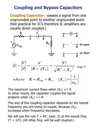
Coupling and Bypass Capacitors. Coupling Capacitor : -passes a signal from one ungrounded point to another ungrounded point. (Not practical for IC’s therefore IC amplifiers are usually direct coupled.). (eqn.1). The maximum current flows when |X C | << R

Coupling and Bypass Capacitors
E N D
Presentation Transcript
Coupling and Bypass Capacitors Coupling Capacitor: -passes a signal from one ungrounded point to another ungrounded point. (Not practical for IC’s therefore IC amplifiers are usually direct coupled.) (eqn.1) The maximum current flows when |XC| << R In other words, the capacitor couples the signal properly when |XC| << R The size of the coupling capacitor depends on the lowest frequency you are trying to couple, because |XC| increases when frequency decreases. We will use the rule T = RC (eqn. 2) at the lowest freq. (T = 1/f). (All other freq. will be well coupled.)
Coupling and Bypass Capacitors Example: To couple freq. in the range 20 Hz to 50kHz. The lowest freq. = 20 Hz T = 1/20 = 0.05 sec If the total resistance in a one loop circuit is 10kW, the coupling capacitor must satisfy T = RC. 0.05 = 10k X C C = 0.05/10k = 5 mF Another widely used rule is to keep |XC| < (1/10) R In this case Bypass Capacitor: -similar to coupling capacitor except it couples an ungrounded point to a grounded point. Eqns. (1) and (2) still apply.
Example: The input signal in the Figure can have a frequency between 10Hz and 50khz. Find the size of the coupling capacitor. Coupling and Bypass Capacitors 24k | |12k = 8k and Thevenize cct. to the left of the capacitor RTH =2k for the lowest freq. Þ Example: We want an AC ground on point A in the Figure. Find the size of the bypass capacitor Þ We need at least 800 mF
AC Equivalent Circuits and Frequency Response low-frequency high-frequency mid-frequency Up until now all of the small-signal AC equivalent circuits we have used have been mid-frequency band models. Low-frequency AC Equivalent Circuit CEAmplifier Fig. 7.14 p. 609
AC Equivalent Circuits and Frequency Response We will use a simplified analysis approach. (An exact analysis could be done using SPICE) To determine wL, the lower 3db frequency: First set Vs to zero, CE and CC2 to infinity and find the resistance RC1 seen by CC1. RC1 = RS + [RB || (rx + rp )] Next set CC1 and CC2 to infinity and determine the resistance R’E seen by CE Set both CC1 and CE to infinity and find the resistance seen by CC2 RC2 = RL + (RC || ro) An approximate value for the lower 3db freq. can now be found now that the equivalent RC time constants are known.
High–frequency model for CE Amplifier (a) High –Freq. Model (CE) (b) Simplified circuit (Thevenin theorem)
This circuit can be further simplified using Miller’s theorem. In our case and Can be replaced by a capacitor Thus connected from terminal B’ to ground. B’ Notice that the input forms a simple RC low-pass filter. The break freq. is given by where is the total capacitance in the input loop. Above fH the gain of the amplifier rolls off at 20 db/decade.
Example: CE Amplifier The hybrid pi parameters are: Also In the high-freq. equivalent circuit model we have: