Download
1 / 1
10 likes | 136 Views
The CRDS cavity: Effective absorption path length: 350 m Cavity beam waist: 1.72 mm Spot size on the cavity mirrors: 2.4 mm FSR :150 MHz; Fundamental mode FWHM: 100 kHz

E N D
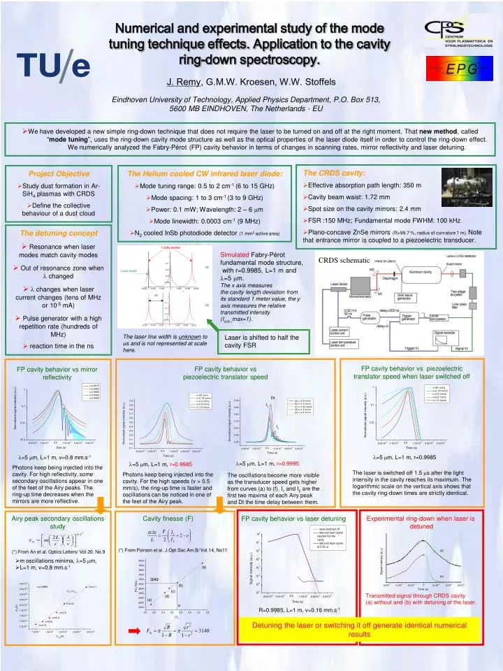
The CRDS cavity: • Effective absorption path length: 350 m • Cavity beam waist: 1.72 mm • Spot size on the cavity mirrors: 2.4 mm • FSR :150 MHz; Fundamental mode FWHM: 100 kHz • Plano-concave ZnSe mirrors (R>99.7 %, radius of curvature 1 m). Note that entrance mirror is coupled to a piezoelectric transducer. Project Objective • Study dust formation in Ar-SiH4 plasmas with CRDS • Define the collective behaviour of a dust cloud The Helium cooled CW infrared laser diode: • Mode tuning range: 0.5 to 2 cm-1 (6 to 15 GHz) • Mode spacing: 1 to 3 cm-1 (3 to 9 GHz) • Power: 0.1 mW; Wavelength: 2 – 6 m • Mode linewidth: 0.0003 cm-1 (9 MHz) • N2 cooled InSb photodiode detector (1 mm2 active area) CRDS schematic FP cavity behavior vs piezoelectric translator speed when laser switched off FP cavity behavior vs piezoelectric translator speed FP cavity behavior vs mirror reflectivity =5 m, L=1 m, v=0.8 mm.s-1 =5 m, L=1 m, r=0.9985 =5 m, L=1 m, r=0.9995 =5 m, L=1 m, r=0.9985 Photons keep being injected into the cavity. For high reflectivity, some secondary oscillations appear in one of the feet of the Airy peaks. The ring-up time decreases when the mirrors are more reflective. The laser is switched off 1.5 s after the light intensity in the cavity reaches its maximum. The logarithmic scale on the vertical axis shows that the cavity ring-down times are strictly identical. Photons keep being injected into the cavity. For the high speeds (v > 0.5 mm/s), the ring-up time is faster and oscillations can be noticed in one of the feet of the Airy peak. The oscillations become more visible as the transducer speed gets higher from curves (a) to (f). I1 and I2 are the first two maxima of each Airy peak and Dt the time delay between them. Airy peak secondary oscillations study Experimental ring-down when laser is detuned FP cavity behavior vs laser detuning Cavity finesse (F) (*) From An et al. Optics Letters/ Vol.20, No.9 • m oscillations minima, =5 m, • L=1 m, v=0.8 mm.s-1 (*) From Poirson et al. J.Opt.Soc.Am.B/ Vol.14, No11 Transmitted signal through CRDS cavity (a) without and (b) with detuning of the laser. R=0.9985, L=1 m, v=0.16 mm.s-1 Detuning the laser or switching it off generate identical numerical results Numerical and experimental study of the mode tuning technique effects. Application to the cavity ring-down spectroscopy. J. Remy, G.M.W. Kroesen, W.W. Stoffels Eindhoven University of Technology, Applied Physics Department, P.O. Box 513, 5600 MB EINDHOVEN, The Netherlands - EU We have developed a new simple ring-down technique that does not require the laser to be turned on and off at the right moment. That new method, called “mode tuning”, uses the ring-down cavity mode structure as well as the optical properties of the laser diode itself in order to control the ring-down effect. We numerically analyzed the Fabry-Pérot (FP) cavity behavior in terms of changes in scanning rates, mirror reflectivity and laser detuning. • The detuning concept • Resonance when laser modes match cavity modes • Out of resonance zone when changed • changes when laser current changes (tens of MHz or 10-5 mA) Pulse generator with a high repetition rate (hundreds of MHz) • reaction time in the ns Simulated Fabry-Pérot fundamental mode structure, with r=0.9985, L=1 m and =5 m. The x axis measures the cavity length deviation from its standard 1 meter value, the y axis measures the relative transmitted intensity (Iout_max=1). The laser line width is unknown to us and is not represented at scale here. Laser is shifted to half the cavity FSR