Download

1 / 23
230 likes | 429 Views
ARIES-CS Maintenance Scheme and Blanket Design for Modular Approach. Presented by A. R. Raffray University of California, San Diego L. El-Guebaly S. Malang D. K. Sze X. Wang and the ARIES Team ARIES Meeting Hilton Garden Inn, Livermore, CA May 6-7, 2003. Outline.

E N D
ARIES-CS Maintenance Scheme and Blanket Design for Modular Approach Presented by A. R. Raffray University of California, San Diego L. El-Guebaly S. Malang D. K. Sze X. Wang and the ARIES Team ARIES Meeting Hilton Garden Inn, Livermore, CA May 6-7, 2003
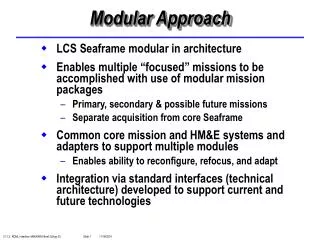
Outline • Summarize engineering plan of action • Modular maintenance approach • Modular design with SiCf/SiC and Pb-17Li • Preliminary discussion of other maintenance approaches • Future work
Proposed Plan for Engineering Activities Machine Parameters and Coil Configurations Maintenance Scheme 2 Maintenance Scheme 1 Maintenance Scheme 3 Evolve in conjunction with scoping study of maintenance scheme and blkt/shld/div. configurations Blkt/shld/div. 1 Blkt/shld/div. 2 Blkt/shld/div. 3 Blkt/shld/div. 1 Blkt/shld/div. 2 Blkt/shld/div. 3 Blkt/shld/div. 1 Blkt/shld/div. 2 Blkt/shld/div. 3 Year1 Optimize configuration and maintenance scheme Optimization in conjunction with maintenance scheme design optimization Optimize configuration and maintenance scheme Optimize configuration and maintenance scheme Year 2 Overall Assessment and Selection Year 3 Detailed Design Study and Final Optimization
Engineering Activities: Year 1 • Perform Scoping Assessment of Different Maintenance Schemes and Design Configurations - Three Possible Maintenance Schemes: 1. Sector replacement including disassembly of modular coil system (e.g. SPPS, ASRA-6C) 2. Replacement of blanket modules through maintenance ports arranged between all modular coils (e.g. HSR) 3. Replacement of blanket modules through small number of designated maintenance ports (using articulated boom) - Each maintenance scheme imposes specific requirements on machine and coil geometry Some initial thoughts for discussion Preliminary port size evaluation Current focus
Engineering Activities: Year 1 • Scoping analysis of possible blanket/shield/divertor configurations compatible with maintenance scheme and machine geometry, including the following three main classes: 1. Self-cooled liquid metal blanket(LiPb) (might need He-cooled divertor depending on heat flux) a) with SiCf/SiC b) with insulated ferritic steel and He-cooled structure 2. He-cooled liquid breeder blanket (or solid breeder) with ferritic steel and He-cooled divertor 3. Flibe-cooled ferritic steel blanket (might need He-cooled divertor depending on heat flux) - Evolve coil configuration(s) - Material and thicknesses - Radius of curvature, shape - Space and shielding requirements This presentation Presented at last meeting (PPPL, MIT)
Proposed Analysis Procedure • Start with NCSX-based coil and plasma shape with 3-field period (From Long-Poe Ku’s memo) • Perform scoping maintenance scheme & configuration analysis • Need divertor guidelines (heat load, geometry)
Plasma Access for Articulated Boom Between Ports for Modular Maintenance Approach With Limited Number of Ports • ITER modular maintenance approach - Rail system - Transporter from port to ~module plane on rail - Articulated boom to replace module • CS configuration makes a rail system very challenging - “Roller coaster” system - Perhaps single rail but only to provide support for boom when extended, not for transporter to carry module to and from port - Preferable to design for module replacement using articulated boom only if possible
• Could use additional ports if required - Depending on access for module removal in toroidal direction over region serviced by port Modular Design Approach Using Articulated Boom • From EDITH-system*, boom built with: - a total length of ~ 10m - a reach of +/- 90° in NET - pay load of 1 ton - maximum height of 2 m • Current ARIES-CS modular design based on comparable parameters for 3 ports (horizontal or vertical) - half field period length ~ 9 m - minor radius =1.85 m (local plasma height varies over about 1.5-3.5 m) - Weight of empty module < 1 ton *Experimental -In-Torus Maintenance System for Fusion Reactors, FZKA-5830, Nov. 1966.
Plasma Access for Articulated Boom Between Ports for Modular Maintenance Approach With Limited Number of Ports • Final number of ports, largest module size and degree of freedom of articulated boom (probably with at least 3-4 “elbows”) would depend on toroidal access through plasma space between port and furthest serviced region - If required, optimization between penalty of increasing reactor size and maintenance and module design considerations
Blanket Modular Design Approach Using SiCf/SiC as Structural Material and Pb-17Li as Breeder/Coolant Based on ARIES-AT concept • High pay-off, higher development risk concept - SiCf/SiC: high temperature operation and low activation - Key material issues: fabrication, thermal conductivity and maximum temperature limit • Replaceable first blanket region • Lifetime shield (and second blanket region in outboard) • Mechanical module attachment with bolts - Shear keys to take shear loads (except for top modules) • Example replaceable blanket module size ~2 m x 2 m x 0.25m (~ 500-600 kg when empty) consisting of a number of submodules (here 10)
• Side wall of adjacent submodules pressure balanced, except for each end submodule where thicker side walls are required to accommodate the pressure • Mechanical attachment between two modules also shown Blanket Module Configuration Consists of a Number of Submodules Submodule configuration • Curved first wall for better Pb-17Li pressure (<~2 MPa) accommodation • 4 mm thick SiCf/SiC first wall with 1 mm CVD SiC coating • Hoop stress ~ 60 MPa
Coolant Flow and Connection for ARIES-CS Blanket Modular Design Using SiCf/SiC and Pb-17Li • Two-pass flow through submodule - First pass through annular channel to cool the box - Slow second pass through large inner channel • Helps to decouple maximum SiCf/SiC temperature from maximum Pb-17Li temperature - Maximize Pb-17Li outlet temperature (and cycle efficiency) - Maintain SiCf/SiC temperature within limits • Use of freezing joint behind shield (and possibly vacuum vessel) for annular coolant pipe connection - Inlet in annular channel, high temp. outlet in inner channel
Pb-17Li Coolant Coupled with Brayton Power Cycle • Best near-term possibility of power conversion with high efficiency • Maximize potential gain from high-temperature operation with SiCf/SiC • Compatible with liquid metal blanket through use of HX Cycle Efficiency Increases with Maximum Cycle He Temperature - Compression ratio set to maximize cycle efficiency in each case - For TSiC/SiC < 1000°C, Max. THe,cycle ~ 900°C and hcycle~ 0.55 - Compression ratio is additional control knob
Some flexibility in setting cycle compression ratio, and inlet HX He temp. (dictating inlet blanket Pb-17Li inlet and max. SiCf/SiC temp.) with minimal decrease in cycle efficiency temperature HX Inlet He Temperature (and, hence, Power Core Pb-17Li Inlet Temperature) Can Be Set by Adjusting Cycle Compression Ratio
Maximum SiC/SiC Temperature Can be Reduced by Decreasing the Annular Channel Thickness, but with a Pressure Drop Penalty
Temperature Distribution in Example ARIES-CS Blanket Modular Design Using SiCf/SiC and Pb-17Li • Pb-17Li Inlet Temperature ~ 699°C • Pb-17Li Outlet Temperature ~ 1100°C • Maximum SiC/SiC Temperature ~ 970 °C • Maximum SiC/LiPb Temperature ~ 900 °C
Typical Parameters for Example ARIES-CS Blanket Design with SiCf/SiC and Pb-17Li (Not fully optimized yet)
Modular Maintenance Approach with Ports Between Each Coil • Minimum Port Sizes - 1.6 m x 2.3 m and 1.2 m x 5.0 m - Quite limiting constraint on size of module - Desirable to accommodate ~2 m x 2 m x 0.25 m module • Unless reactor size (and port size) is increased, this maintenance scheme seems marginal and a modular maintenance scheme through fewer larger ports is preferable
Sector-Like Maintenance Approach • Based on current example machine configuration, the following sector removal seems possible - 3 sectors consisting of 4 coils each - 3 sectors consisting of 2 coils each - Must remove two larger sectors first and then smaller sector - Complex maintenance process - Size and number of maintenance sectors would change based on several parameters including: - size of machine - toroidal protrusion of coil on adjacent coil - size coil + casing - Guidance needed on these, e.g. - confirmation of smaller size coil + casing (20 cm?) - physics wise how much do we lose with ~10’s cm less toroidal coil protrusion?
Some Initial Thoughts for Sector-Like Maintenance Approach Based on Disasembling the Modular Coil System (S. Malang) 1. Is it feasible to heat up the coil system prior to disassembly or is it necessary to design the coil system for “cold” maintenance - If heating up the system is feasible (for blanket replacement), how much additional time would be required for such an operation? - Impact of this additional time will depend on frequency of blanket replacement - e.g. a cool-down period of ~1 month years would probably be acceptable for blanket replacement (~3MW/m2, 0.85 load factor-->200 dpa steel) every ~8 years of operation (~1% impact on availability) 2. Which kind of connections between the cold coil system and a support at ambient temperature can be designed to carry the total weight of coils + supporting structure? - The issue here is the heat flow to the cold system through the supporting legs. - More serious problem for LTSC’s - Is a requirement for the cryogenic plant of ~1 MW acceptable (corresponding to ~1000W of heat removal)?
Some Initial Thoughts for Sector-Like Maintenance Approach Based on Disasembling the Modular Coil System (cont.) 3. How can the coil system be supported to react the radial forces pulling it toward the centre of the system? • These are by far the largest forces acting on the coils. - Up to 350MN per coil for the SPPS- Stellarator, reacted by a ring with a 5-m inner radius of and a 3-m wall thickness• Such large forces cannot be transferred from a cold to a warm component (through an insulation). • Therefore, the coil winding, housing, and the supporting ring in the centre have to be operated at a uniform cryogenic temperature. • Already challenging to design such a system without the requirement to allow for disassembling the coils for blanket replacement. • This issue needs more attention than previously paid by a number of Stellarator reactor studies.
Some Initial Thoughts for Sector-Like Maintenance Approach Based on Disasembling the Modular Coil System (cont.) 4. How large are the forces between neighboring coils, and how can they be reacted?• For planar coils with equal current flow these forces are balanced, but if one coil fails, large forces would act on the neighboring coils. • For a system with non-planar coils, forces between neighboring coils exist but are balanced within each field period in the case of a Stellarator . • All coil windings of a field period could be placed in grooves of a common support tube strong enough to balance the lateral forces of the coils. • If this is feasible, these support tubes would be “stand-alone elements” not requiring force transfer between field periods. • This would be advantageous for blanket maintenance but at the expense of having to move a huge unit for blanket replacement (the size would be reduced if it could be done over half a field period) 5. How can the weight of the blanket+neutron shield be transferred to the base structure of the reactor?• For the above-mentioned case with a strong supporting tube per field period, the weight of the cold elements (winding + supporting tube, ~ 5000 tonnes) must be transferred to the vacuum vessel through supporting legs with minimum heat conduction area • The weight of the “warm” components surrounding the plasma (FW, breeding blanket, reflector, neutron shield, ~ 10,000 tonnes) ) must be transferred to the fundament of the vacuum vessel via “warm” leg, reaching through openings in the “cold” support tubes of the coils. • There has to be insulation around these legs, and the legs can be used to house the coolant access tubes for the blankets.
Guidance Needed on Several Questions, Including: 1. Coil: HTSC or LTSC2. Coil: Confirm thickness of windings+casing3. Coil: Demountable or not4. Coil/Physics: What is the penalty of shaving off ~10 cm’s radially to facilitate access for sector maintenance5. Coil/Physics: What is the penalty of changing the number of field periods (e.g. going from 3-field to 2-field or 4-field periods)6. Divertor: Location, heat loads, particle fluxes?7. Starting Point Configuration: Need revised consistent set of power density, machine size, plasma parameters and magnetic field