Download
1 / 8
80 likes | 241 Views
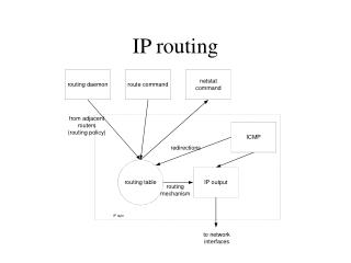
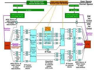
User Space. Interrupt. User Socket Layer Kernel Socket Layer. User Layer CB Socket Kernel Layer CB Socket. Kernel Space. tcp/udp_input. tcp/udp_output. ip_input. ip_output. Software Interrupt Level APIC Driver. Software Interrupt Level APIC Driver. SW Int Cntxt. APIC Descs. &

E N D
User Space . . . . . . . . . . . . Interrupt . . . . . . User Socket Layer Kernel Socket Layer User Layer CB Socket Kernel Layer CB Socket Kernel Space tcp/udp_input tcp/udp_output ip_input ip_output Software Interrupt Level APIC Driver Software Interrupt Level APIC Driver SW Int Cntxt APIC Descs. & AAL5 frame in mbuf data buffers HW Int Cntxt PluginCtl. Unit Register Access Monitor- ing, Basic IP Header Proc., PacketClassi- ficationand Routing Register Access Xmit Input Side Rcv Input Side . . . . . . PacketScheduler . . . . . . APIC APIC Register Access IP Opt Register Access APIC Driver Rcv Side APIC Driver Xmit Side Resource Controller IP Path Xmit Output Side PacketScheduler Rcv Output Side . . . . . . Classified IP Packet in chained mbufs with route APIC Descs. & AAL5 frame in mbuf data buffers APIC Descs. & AAL5 frame in mbuf data buffers IP Packet in chained mbufs IP Packet in chained mbufs
31 24 16 8 0 Match/Checksum - - - - V I S O E C L X T Y BufAddrLo BufLen NextDesc BufAddrHi BufAddrLo BufAddrHi Data Structures: APIC Descriptor O: Read Only, E: EOF, C: CRC OK, T: Type, Y: Valid Bits Buffer Length or Amount Left Unused Index into Desc Table Physical Address of Data Buffer Buffer Data Byte 0 Byte Buflen - 1
0xCAFE 0xCAFE 0xCAFE - - - - - - - - - - - - V V V I I I S S S O 0 O 0 O 0 E 0 E 0 E 0 C 0 C 0 C 0 L L L X X X T 00 T 00 T 00 Y 11 Y 11 Y 11 2016 2016 2016 NextDesc NextDesc NextDesc BufAddrLo BufAddrLo BufAddrLo MBUF BufAddrHi BufAddrHi BufAddrHi m_data Step 0.1: APIC Driver Initializes Desc. and Buffers Structures Pool X Chain Head MBUF m_data
Rcv Input Side . . . APIC Driver Rcv Side APIC Register Access Rcv Output Side . . . APIC Descs. & AAL5 frame in mbuf data buffers 0xCAFE - - - - V I S O 0 E 0 C 0 L X T 00 Y 01 Interrupt 0 NextDesc = 0 BufAddrLo = 0 BufAddrHi = 0 Step 0.2: APIC Driver Initializes Descriptors and Buffers For each VC that has been opened, the APIC Driver initializes the per VC Current Descriptor register in the APIC hardware to point to a descriptor that is marked DONE_INVALIDLINK. Thus when the APIC starts getting data for this VC, it will be forced to go off and grab the next available Descriptor and re-write the current one with a pointer to the new one. The APIC driver keeps a structure for the VC that keeps a pointer to this chain (our per VC queue!). VC 101 Queue Y: Valid Bits (01: DONE_INVALIDLINK)
Rcv Input Side . . . APIC Driver Rcv Side APIC Register Access Rcv Output Side . . . APIC Descs. & AAL5 frame in mbuf data buffers 0xCAFE 0xCAFE 0xCAFE - - - - - - - - - - - - V V V I I I S S S O 0 O 0 O 0 E 0 E 0 E 0 C 0 C 0 C 0 L L L X X X T 00 T 00 T 00 Y 11 Y 11 Y 11 Interrupt 2016 2016 2016 NextDesc NextDesc NextDesc BufAddrLo BufAddrLo BufAddrLo MBUF BufAddrHi BufAddrHi BufAddrHi m_data Step 0.3: APIC Driver Initializes Descriptors and Buffers Pool X Chain Head MBUF m_data
Rcv Input Side . . . APIC Driver Rcv Side APIC Register Access Rcv Output Side . . . APIC Descs. & AAL5 frame in mbuf data buffers 0xCAFE checksum ??? checksum - - - - - - - - - - - - V V V I I I S S S O 0 O 0 O 0 E 0 E 0 E 1 C 0 C 0 C 1 L L L X X X T 00 T 00 T 00 Y 00 Y 00 Y 11 Interrupt 0 2016 1016 NextDesc NextDesc ??? NextDesc BufAddrLo BufAddrLo BufAddrLo BufAddrHi BufAddrHi BufAddrHi Step 1: APIC Hardware Writes 3016 byte AAL5 Frame to Memory Pool X Chain Head VC 101’ Queue Need to show how they get linked to the per VC queue that exists.
. . . . . . Step 2: APIC Driver Chains Mbufs into IP Packet PacketClassi- ficationand Routing Rcv Input Side . . . APIC Driver Rcv Side APIC Register Access Rcv Output Side . . . APIC Descs. & AAL5 frame in mbuf data buffers IP Packet in chained mbufs