Download
1 / 52
520 likes | 550 Views
Learn about the refrigeration cycle, ice production, water quality, and maintenance of flake and cube ice machines, including functions, controls, and ice shapes. Improve your knowledge for efficient ice making operations.

E N D
UNIT 27 COMMERCIAL ICE MACHINES
UNIT OBJECTIVES • 1.Describe the refrigeration cycle for flake ice machines • 2. Explain the functions of the harvest, flush cycle and bin controls • 3. Describe production and performance charts for ice machines • 4. Explain how various shapes of ice are produced
5. Explain an ice machine’s sequence of operations 6. Discuss the importance of water quality in the ice making process 7. Discuss the concepts of cleaning, sanitizing and filtration
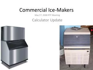
27.1 PACKAGED-TYPE ICE MAKING EQUIPMENT • 1. Most package ice makers are air cooled , Ice is formed on the evaporator and then harvested • 2. Ice is stored in a bin located below the unit at 32 degrees F • 3. Melting ice provides the cooling in the bin • 4. Water must be supplied to the unit and a drain must be furnished for the bin • (Two types: Flake ice & Cube ice)
27.2 MAKING FLAKE ICE • 1. Formed in a vertical cylinder surrounded by the evaporator, use flights as a cutting surface, forms flakes (fig.27.1) • 2. An auger scrapes the ice from the cylinder walls (fig.27.2) • 3. Ice is removed and stored in a bin (fig.27.3) • 4. Water level is critical and maintained by a float on the top of the evaporator (fig.27.5)
Rotating auger Reservoir Evaporator Ice chute Water supply to refrigerated cylinder
Ice forms on the inside surface of the refrigerated cylinder
As the auger rotates, the flights scrape the ice, forming flakes Ice flakes in the chute falling into the bin
27.2 MAKING FLAKE ICE • 1. Evaporator and auger surfaces must be clean and free of score marks • 2. Auger turns at a speed of 9 to 16 rpm • 3. Speed is reduced by a gear reduction drive • 4. Gear assembly prone to failure • 5. Auger should not wobble • 6. Annual equipment cleaning prolongs system life
WATER FILLING SYSTEMS • Conductivity probe or water sensor in water reservoir. 1.Water level sensed by the probe 2.Electric water valve opens when the water level is low (fig.27.10a,b)
Water inlet Float valve Water level Reservoir Overflow Water to refrigerated cylinder
MAKING FLAKE ICE – WATER FILL SYSTEM(fig.27.11) • Dual float switch and water control valve 1.Float switch controls a solenoid valve 2.Solenoid controls the water valve 3.System shuts down if there is a low water situation
FLUSH CYCLESpg.690 • 1.Minerals can cause maintenance problems and poor ice quality • 2.Periodic flushing helps remove mineral deposits • 3.Flushing cycles are often computer controlled • 4.Can be automatic or manual • 5.Some systems drain whenever system cycles off • Note: see (fig.27.12) for flush timer, flush switch and flush water solenoid valve.
BIN CONTROLS pg.690 • 1.When bin is full, ice-making process must stop • 2.Mechanical flapper device senses backed-up ice • 3.Infrared electric eye • a.Sensors can “see” each other when ice level is low • b.When ice builds up, sensors cannot see each other • 4.Sonar waves reflected to the control from the ice • 5.Thermostats are liquid-filled bulbs
ICE PRODUCTION AND PERFORMANCE DATA (pg.692) • 1.Ice production drops as water temperature increases a.More energy is required to cool and freeze ice • 2.Ice production decreases as ambient temperature increases • a.More heat gain on the ice • (fig.27.13)
ICE FLAKE SIZE ADJUSTMENT (pg.693) • 1.More diverse machines • 2.Adjustment of the ice cutter • 3.Small, medium, or large flakes can be produced • 4.Cutting heads can be changed • 5.Extrusion heads: cubelet and flaked ice from same machine
27.3 MAKING CUBE ICE • Flat ice cut into cubes (pg.693) 1.Ice formed on a flat evaporator 2.Ice thickness is sensed and monitored 3.Ice sheet slides onto a wire grid 4.Grid is heated 5.Grid cuts the ice into the desired shape
(fig.27.15) Water manifold Water flowing over evaporator Ice Evaporator tubes Pump
MAKING CUBE ICE • Cube ice 1.Water is flooded over an evaporator with individual cups 2.Cups are shaped like the cubes 3.Ice is formed and then stored in a • 4. Most common are vertical evaporator • Eyeglass-shaped ice cubes (fig.27.18) 1.Water flows over evaporator by gravity 2.Ice fallsout of the cups during harvest or defrost
Evaporator tubes Ice cups (fig.27.17a-e)
Evaporator tubes Water spray Rotating water spray bar
Ice cubes are formed Evaporator tubes Water spray Rotating water spray bar
Hot gas in evaporator tubes for harvest Hot gas frees the ice cubes from the evaporator
MAKING CUBE ICE • Crescent-shaped ice cubes (fig.27.19) 1.Water runs over evaporator plates 2.As water freezes, the water level drops 3.When water level is low enough, harvest is initiated 4.Hot discharge gas is directed through the evaporator 5.Cubes begin to melt 6.Cubes slide down the plate and into the bin
MAKING CUBE ICE • Cell-type ice cubes (fig.27.20) 1Vertical evaporator 2.Water flows over the coil by a water pump 3.Ice will form in the cells, and bridges will form between the cells 4.When correct bridge thickness is obtained, harvest is initiated 5.Water level in reservoir controlled by a float switch or probe
Water distribution tube Water flows over the evaporator Vertical evaporator
Ice begins to form in each individual cell Water flows over the evaporator
Ice cubes are formed Water flows over the evaporator
Bridge thickness sensor (fig.27.25a) Ice cubes in evaporator
Bridge thickness sensor Ice bridge is sensed by the control Ice bridge between cubes (fig.27.25a)
MAKING CUBE ICE • Ice harvests • 1.Hot discharge gas piped to the evaporator • 2.Suction-line accumulators are used • 3.Liquid flood back can damage the compressor • 4.If water is too pure, harvest may not be initiated • 5.Weep holes help separate the ice from the evaporator • 6.Dump valve may be energized during harvest • 7.Release of ice must be detected
ICE MACHINE PRESSURE CONTROLS (pg.710) • Fan cycling controls opens and closes to maintain desired head pressure • High pressure switch (Safety device) 1.Will open if head pressure reaches unsafe levels • Low pressure controls 2.De-energize system if suction pressure drops too low • Reverse-acting low pressure switches 1.Close contacts on a drop in pressure 2.Used to initiate the harvest cycle
27.4 MICROPROCESSORS • 1.Store the sequence of operations for the system • 2.Can perform self-diagnostics • 3.Make systems more reliable, easier to troubleshoot and less complicated • 4. Small computer, known as integrated circuit controllers • 5.Technician should know how to INPUT/OUTPUT troubleshoot using external terminals • 6.Microprocessor’s self diagnostics and error codes • 7.Microprocessor’s history or summary • (fig.27.46a)
27.5 MAKING CYLINDRICAL ICE • 1.Utilizes a tube within a tube evaporator • 2.Refrigerant flows in the outer tube, water in the inner tube • 3.Ice begins to form and the water tube begins to close up • 4.Water pressure begins to increase • 5.At a predetermined pressure, harvest is initiated • 6.Hot gas is piped to the evaporator • 7.Water pressure pushes ice from the tube
Suction gas to compressor Evaporator for making cylindrical ice Metering device
Refrigerant to compressor Water pumped through evaporator Refrigerant to evaporator
Refrigerant to compressor Water flow is restricted as ice forms Ice forms on the inside surface of the tube Refrigerant to evaporator
Refrigerant to compressor Water flow is restricted as ice forms Ice forms on the inside surface of the tube Refrigerant to evaporator
Hot gas for harvest Water flow is restricted as ice forms Ice forms on the inside surface of the tube Hot gas for harvest Harvest is initiated when the pump pressure reaches the predetermined point
Cylindrical ice is pushed from the tube Hot gas for harvest Water pressure pushes ice from the tube Hot gas for harvest Harvest is initiated when the pump pressure reaches the predetermined point
27.6 WATER AND ICE QUALITY • 1.Ice is a food source • 2.Quality of ice depends on the quality of the water used • 3.Water quality varies greatly • a.Sediment • b.Scale • c.Iron • d.Total dissolved solids • e.pH • f.Chlorine
ICE QUALITY (pg.720) • 1.Measured in percent of hardness • 2.Hardness represents thermal cooling capacity • 3.The harder the ice, the more cooling ability the ice has • 4.Harder ice is denser and will last longer • 5.Calorimeter test to determine ice hardness • 6.Cleaner ice machines + Pure water = Hard Ice
SANITIZING AND CLEANING (pg.721) • 1.Helps eliminate bacteria, viruses, and protozoa • 2.Airborne organisms are more common than those in the water supply • 3.Cleaning solutions are food-grade acids • 4.Scale removers and sanitizers should not be used together • 5.Once a month for sanitizing
WATER FILTRATION AND TREATMENT (pg.722) • 1.75% of system problems are water related • 2.Water treatment reduces cleaning/sanitizing frequency • 3.Suspended solids are easy to remove with mechanical filters • 4.Dissolved metals and minerals require RO, distillation, or de-ionization • 5.Chemicals are removed with carbon filtration • 6. Uses polyphosphates to inhibit calcium or lime scale • 7. Always wear eye protection when working with chemicals
27.7 PACKAGED ICE MACHINE LOCATION • 1.Most ice makers are designed to operate in locations that are between 40° and 115°F • 2.Outdoor units may not function properly if temperature falls below 40°F • 3.Outdoor units often have head pressure controls • 4.Indoor units must have enough airflow through the condenser coil
Installation of a package machine • Set and level the machine • Supply power, plug or hard wire • Provide a water supply • Provide a drain for ice bin
27.8 TROUBLESHOOTING ICE MAKERS • Water circuit problems • 1.Water level is critical and should be properly set • 2.Seat on the float valve is a common source for leaking • 3.Water can leak in to the bin and melt ice • 4.Check float seat for leaks when the bin is empty • 5.Follow manufacturer guidelines regarding evaporator water flow • 6.Supply water must be of good quality
TROUBLESHOOTING ICE MAKERS • High-side pressure problems • 1.Poor condenser air circulation • 2.Recirculating condenser air • 3.Dirty condenser • 4.Defective condenser fan motor • 5.System overcharge • 6.Noncondensables in the system
TROUBLESHOOTING ICE MAKERS • Low-side pressure problems 1.Low refrigerant charge or improper water flow 2.Mineral deposits on evaporator 3.Restricted drier or liquid line 4.Defective metering device 5.Moisture in the refrigerant 6.Inefficient compressor 7.Starved evaporator
TROUBLESHOOTING ICE MAKERS • Electrical problems • Defrost problems 1.larger-than-normal ice shapes (delayed or no defrost) 2.No ice production (harvest will not terminate) 3.No ice production (water pump problems) 4.Improper supply voltage – out of range 5.Overheating of the power cord