
IFMIF-DONES: Advanced Neutron Source Workshop
E N D
Presentation Transcript
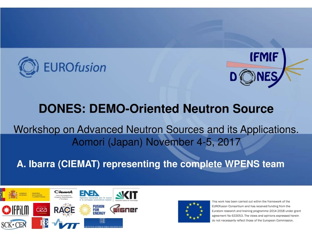
DONES: DEMO-Oriented Neutron SourceWorkshop on Advanced Neutron Sources and its Applications. Aomori (Japan) November 4-5, 2017 A. Ibarra (CIEMAT) representing the complete WPENS team February 2005
Outline • DONES objective and overallapproach • AcceleratorSystemssummary • Test Systemssummary • Li systemssummary • RemoteHandling & Buildingsystems • Summary A. Ibarra| Neutron Sources Workshop| Aomori (Japan)| November 4-5, 2017| Page 2
Outline • DONES objective and overallapproach • AcceleratorSystemssummary • Test Systemssummary • Li systemssummary • RemoteHandling & Buildingsystems • Summary A. Ibarra| Neutron Sources Workshop| Aomori (Japan)| November 4-5, 2017| Page 3
Neutronsourcerequirements Along the time, it has been widely recognized that a fusion-like neutron source is needed for fusion materials qualification both for DEMO and the power plant development The requirements are to produce fusion-like neutrons • Intensity large enough to allow accelerated (as compared to DEMO) testing, • Damage level above the expected operational lifetime, • Irradiation volume large enough to allow the characterization of the macroscopic properties of the materials of interest required for the engineering design of DEMO (and the Power Plant) Requirementsbasedon EU DEMO needs > 10 dpa(Fe)/fpy 20 dpa(Fe) in 1.5 y 50 dpa(Fe) in 3.5 y 300 cm3 The most feasible approach based on Li(d,xn) sources The IFMIF-DONES project!!! The IFMIF project since 90´s A. Ibarra| Neutron Sources Workshop| Aomori (Japan)| November 4-5, 2017| Page 4
Whatis IFMIF-DONES? It is the minimum neutron source required to fulfill the materials fusion-like irradiations needs of DEMO IFMIF-DONES (Demo-OrientedNeutronSource) • Main technical characteristics • Based on IFMIF Preliminary Engineering Design simplified as much as possible: • One full energy (40 MeV) accelerator with angular incidence • Full size IFMIF Test Cell: only half cooling needed • Full size IFMIF Li loop: only half cooling, half purification system needed • Reduced number of irradiation modules to be used: no need of Tritium online measurements and strong simplification of Pipes & Cables Plugs • Minimum irradiated materials (modules, target,…) manipulation in the plant: irradiated materials transferred to external facilities, if possible • Waste management reduced to the minimum • Upgrade to full IFMIF could be feasible A. Ibarra| Neutron Sources Workshop| Aomori (Japan)| November 4-5, 2017| Page 5
Design process of IFMIF-DONES Plant IFMIF-EVEDA validation activities: Orai loop, Heloka, Lifus6, LIPAc IFMIF-DONES validation activities Critical technical issues analysis (quench tank location, TA approach, AC configuration,… WPENS Project timeline IFMIF EDR 2013 Plant and systems requirements definition Design guidelines Boundaries and interfaces identification Implementation of design choices Systems design Integrated analysis IFMIF-DONES Conceptual Design Report 2014 Preliminary Safety AnalysisReport Reference Design Secondhalf2016 PreliminaryEngineering Design report2017 A. Ibarra| Neutron Sources Workshop| Aomori (Japan)| November 4-5, 2017| Page 6
IFMIF-DONES PlantConfiguration A. Ibarra| Neutron Sources Workshop| Aomori (Japan)| November 4-5, 2017| Page 7
Outline • DONES objective and overallapproach • AcceleratorSystemssummary • Test Systemssummary • Li systemssummary • RemoteHandling & Buildingsystems • Summary A. Ibarra| Neutron Sources Workshop| Aomori (Japan)| November 4-5, 2017| Page 8
Acceleratorsystemssummary SRF cryomodule RFQ • 175 MHz, 5MW, 125 mA, CW, highavailability: One of the more powerfulaccelerators in theworld. WaitingforvalidationresultsfromLIPAc (Rokkasho) • Very similar to the IFMIF onebutsomechangesimplemented…. A. Ibarra| Neutron Sources Workshop| Aomori (Japan)| November 4-5, 2017| Page 9
AS main changes: SRF configuration Reference design for SRF linac system: 5 Cryomodules! Implemented to assure the D final energy and reduced beam losses A. Ibarra| Neutron Sources Workshop| Aomori (Japan)| November 4-5, 2017| Page 10
AS mainchanges: Beamspecificationson target SRF cryomodule RFQ A. Ibarra| Neutron Sources Workshop| Aomori (Japan)| November 4-5, 2017| Page 11
AS mainchanges: Solid state RF LIPAc Project: 2x20kW SS RF chains 50V 1200W LDMOS Transistor Freescale MRFE6VP61K25H New 65V 1800W LDMOS NXP MRFX1K80 (pin-compatible) 2017 2016 • RF source can be tunedforeachcavity • On-operationmaintenanceisfeasible • Higheravailability 2010-2012 A. Ibarra| Neutron Sources Workshop| Aomori (Japan)| November 4-5, 2017| Page 12
Outline • DONES objective and overallapproach • AcceleratorSystemssummary • Test Systemssummary • Li systemssummary • RemoteHandling & Buildingsystemx • Summary A. Ibarra| Neutron Sources Workshop| Aomori (Japan)| November 4-5, 2017| Page 13
Test Systems summary Irradiation module Cooledshieldingplug Ductpenetration A. Ibarra| Neutron Sources Workshop| Aomori (Japan)| November 4-5, 2017| Page 14
Test Systems summary Irradiation module Cooledshieldingplug • Maincharacteristicsdrivenbythepresence of neutrons and Li • Internalcomponentscoolingby He • RemoteMaintenancerequired • Similar tothe IFMIF onebutsomechangesimplemented (orto be implemented)… Ductpenetration A. Ibarra| Neutron Sources Workshop| Aomori (Japan)| November 4-5, 2017| Page 15
Test Systems Changes: Test Cell configuration & others Test Cell configuration: • Enlarged to host the Quench Tank • New volume added to define Li loop fixed points:TC-LS Interface Cell (extended liner) HFTM design: • NaK must be avoided (Na filled proposed) • Improved fabrication methods A. Ibarra| Neutron Sources Workshop| Aomori (Japan)| November 4-5, 2017| Page 16
Test Systems: Progress of engineering design Neutrons Photons Water cooling of concrete walls Detailed design of PCP (including radiation streaming) STUMM module to characterize the facility during the commissioning phase A. Ibarra| Neutron Sources Workshop| Aomori (Japan)| November 4-5, 2017| Page 17
Outline • DONES objective and overallapproach • AcceleratorSystemssummary • Test Systemssummary • Li systemssummary • RemoteHandling and Buildingsystems • Summary A. Ibarra| Neutron Sources Workshop| Aomori (Japan)| November 4-5, 2017| Page 18
Li systemssummary Inlet nozzle FDS Target chamber Beam duct Back-Plate Lithium inlet pipe IISP Oil-Oilsecondary HX TC floor level Outlet nozzle Quench Tank Support structure Oil-Watertertiary HX Lithium outlet pipe Target assembly Inlet pipe fixed point Li-Oiltertiary HX LI mainloop Li monitoring Li purificationloop A. Ibarra| Neutron Sources Workshop| Aomori (Japan)| November 4-5, 2017| Page 19
Li systemssummary Inlet nozzle FDS Target chamber Beam duct • 5 MW powerhandling, 15 m/s Li velocity, remotehandling • Mainrequirements: Li flowstability and Li impurities control • Mainchallengesto be considered: • Target Assemblylifetime • Risk of cavitation, Li evaporation • T (and otherradioactiveions) inventory • Veryrelevantresultsfrom IFMIF/EVEDA validationactivities • Very similar tothe IFMIF onebutsomechangesimplemented… Back-Plate Lithium inlet pipe IISP Oil-Oilsecondary HX TC floor level Outlet nozzle Quench Tank Support structure Oil-Watertertiary HX Lithium outlet pipe Target assembly Inlet pipe fixed point Li-Oiltertiary HX LI mainloop Li monitoring Li purificationloop A. Ibarra| Neutron Sources Workshop| Aomori (Japan)| November 4-5, 2017| Page 20
LS main changes: quench tank design Conditioning grid Stress distribution Stream lines • Quench tank must be located as close as possible to the target assembly outlet to reduce the risk of cavitation • Quench tank must have some internal structure to assure uniform outlet flow with a reduced volume (and stable surface) • Remote maintenance must be feasible A. Ibarra| Neutron Sources Workshop| Aomori (Japan)| November 4-5, 2017| Page 21
LS main changes: Impurities control Purification requirements Hydrogen electrochemical sensor Tritium modelling by Ecosimpro • Review of impurity contents requirements • Purification strategy improved: N trap off-line integrated in the dump tank • Mass transfer modelling • Hydrogen isotopes modelling • Target and Li monitoring diagnostics A. Ibarra| Neutron Sources Workshop| Aomori (Japan)| November 4-5, 2017| Page 22
Outline • DONES objective and overallapproach • AcceleratorSystemssummary • Test Systemssummary • Li systemssummary • RemoteHandling and Buildingsystems • Summary A. Ibarra| Neutron Sources Workshop| Aomori (Japan)| November 4-5, 2017| Page 23
Remote Handling System HFTM & positioningsystemC TA positioning system TA & storagesupport TCCP, USP & LSP Stillagesupportfortooling Stillagesupportfortooling Plugfor IWTC hatc Plugfor TIR hatc • Key and complexsystem • Itrequiresevaluation of maintenanceneeds and dosemaps, identification of alltherequiredoperations, design of common and specifictools, evaluation of theoperations,… A. Ibarra| Neutron Sources Workshop| Aomori (Japan)| November 4-5, 2017| Page 24
Building and Plant Systems Main Building (generic site) Dimensions ~ 160 x 75 ; Three – story Basement/foundation slab, three suspended floors at different elevations, and one additional roof slab Main structural system is formed by a combination of bearing walls, columns, suspended slabs and beams, all of them in-situ cast with concrete. Included and areaforOtherComplementaryexperiments Plant Systems HVAC; Electrical Power System (~45 MVA); Heat Rejection System (~18 MW); Service Water System (Potable/Industrial/Demi); Service Gas Systems (Argon, Helium, Nitrogen, CA) Radioactive Waste Treatment System (Solid, Liquid and Gas/Detritiation) Fire Protection System (Det./ Ext.) A. Ibarra| Neutron Sources Workshop| Aomori (Japan)| November 4-5, 2017| Page 25
Outline • DONES objective and overallapproach • AcceleratorSystemssummary • Test Systemssummary • Li systemssummary • RemoteHandling and Buildingsystems • Summary A. Ibarra| Neutron Sources Workshop| Aomori (Japan)| November 4-5, 2017| Page 26
Summary • A fusion-likeneutronsourceisneeded as soon as possiblefor DEMO design and IFMIF-DONES istheproposedEuropeanalternative to be implemented in thenearfuture • IFMIF-DONES designisbased on IFMIF designevolved to takeintoaccount a reducedscope and resultsobtainedduringtheprototypingphase • Ifeverythingmovesonproperly, construction can start in 2020 • Engineering design for the different systems is progressing steadily. Key results must be obtained from LIPAc in Rokkasho A. Ibarra| Neutron Sources Workshop| Aomori (Japan)| November 4-5, 2017| Page 27
End A. Ibarra| Neutron Sources Workshop| Aomori (Japan)| November 4-5, 2017| Page 28