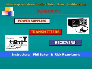
SESSION # 3
SESSION # 3. POWER SUPPLIES. TRANSMITTERS. RECEIVERS. Instructors: Phil Baker & Rick Ryan-Lewis. POWER SUPPLIES. Transformer. Rectifier. Filter. POWER SUPPLIES. Transformer. Power In = Power Out. Power Formula P = VI V = Volts I = Amps.

SESSION # 3
E N D
Presentation Transcript
SESSION # 3 POWER SUPPLIES TRANSMITTERS RECEIVERS Instructors: Phil Baker & Rick Ryan-Lewis
POWER SUPPLIES Transformer Rectifier Filter
POWER SUPPLIES Transformer Power In = Power Out Power Formula P = VI V = Volts I = Amps Output Voltage is directly proportional to turn ratio Output Current is inversely proportional to turn ratio
POWER SUPPLIES Alternating Current (AC)
POWER SUPPLIES Sine Wave
POWER SUPPLIES Half-Wave Rectifier – 1 diode
POWER SUPPLIES Full-Wave Rectifier – 2 diodes
POWER SUPPLIES Full-Wave Bridge Rectifier – 4 diodes
POWER SUPPLIES Filter Capacitor Ripple Filter Capacitor is used to achieve a constant DC voltage with minimum ripple The magnitude of the ripple is inversely proportional to the capacitance of the filter
POWER SUPPLIES Regulator Regulatorensures a constant output voltage for varying current loads and minor fluctuations of the input voltage
Grounded Chassis Interlock Mechanisms Key Operated On/Off Bleeder Resistors POWER SUPPLIES SAFETY As little as 1/10 of an Amp and 30 Volts can be fatal In case of an Emergency TURN OFF THE POWER FIRST !!
Send information – message or baseband signal Must be converted to Radio Frequency (RF) signal TRANSMITTERS • RF Generator/Oscillator: Produces the carrier • Modulator: Converts baseband signal to RF signal • RF Power Amplifier: Increases RF signal power
TRANSMITTERS Continuous Wave (CW) • On-off keying (O.O.K.) • Morse Code is transmitted as an interrupted carrier • Key click filter - choke in series with Key and a capacitor across the contacts suppresses RF clicks Power Supply
Modulation Combines Original information signal RF sine wave – Pure Carrier Types Amplitude Modulation (AM) Frequency Modulation (FM) TRANSMITTERS BANDWITH If useful information is conveyed, then spectrum must be occupied
TRANSMITTERS Amplitude Modulation (AM) Baseband modulating signal RF Generator carrier signal RF Signal from Modulator
TRANSMITTERS Amplitude Modulation (AM) Envelop of carrier must not reach zero USB OVERMODULATION produces Splatter on adjacent frequencies AM signal has 2 symmetrical sidebands Upper sideband - USB Lower sideband -LSB LSB AM signal bandwidth occupies twice the highest frequency sent to the modulator
TRANSMITTERS Single Side Band (SSB) • The carrier and one sideband are eliminated • Requires less power and half the bandwidth Fig. 1 Fig. 2 Fig. 3 Conventional AM Signal Carrier Removed (DSBSC) Unwanted Signal Removed By Balanced Modulator By Sideband Filter
TRANSMITTERS Single Side Band (SSB) Carrier fc suppressed
TRANSMITTERS Single Side Band (SSB) { } fc + fa fc - fa Filter fc + fa Unwanted sideband removed DSBSC
TRANSMITTERS Single Side Band (SSB) Balanced Modulator removes the carrier – (DSBSC) Mixer converts sideband signal to final output frequency 1 4 Sideband Filter removes unwanted sideband Variable Frequency Oscillator determines output frequency 2 3
TRANSMITTERS Frequency Modulation (FM) Baseband modulating signal RF Generator carrier signal Modulated Carrier Signal
Superior noise immunity Ease of tuning High audio quality TRANSMITTERS Frequency Modulation (FM) The maximum limit of the instantaneous frequency in either direction is called the maximum deviation
TRANSMITTERS Frequency Modulation (FM) Frequency multiplier increases both frequency and deviation Over deviation causes out of channel emissions and signal distortion Normal deviation for two-way radio +/- 5 kHz
No message signal – Output is an unmodulated carrier Normal bandwidth 10 – 20 kHz Not used below 29.5 MHz – exceeds bandwidth limits (6 kHz) Mic gain too high (talking too loud or too close)causes nearby frequency interference Reactance modulator connected to an RF Power Amp produces a phase modulation emission TRANSMITTERS Frequency Modulation (FM)
Class A Single sideband AM modulation Good linearity Class C FM modulation Non-linear High efficiency TRANSMITTERS Power Amplifiers Approx ½ of the power supplied to the amplifier stage is released as heat
Quality Parameters Frequency stabilityThe ability of a receiver to stay tuned to an incoming signal for a long period. SensitivityThe ability to receive weak signals. Selectivity The ability to reject signals on adjacent frequencies. The narrower the band pass filter, the "higher" the selectivity. RECEIVERS Receiver Fundamentals
Amplifies the signal from the detector and raises it to a level suitable for driving headphones or a speaker. A transformer is generally used to matchspeaker impedance RECEIVERS Receiver Fundamentals The Audio Stage The Automatic Gain Control (AGC)circuit in AM receivers, maintains constant audio output for varying RF signal strengths The Squelchcircuit mutes audio output when there is no signal
RECEIVERS “Block diagram" of a "superhetrodyne" receiver three amplifiers are shown, the RF amplifier, the IF amplifier, and the AF amplifier.
RECEIVERS The Radio Frequency Amplifier Amplifies input signal to a usable level Ahead of Mixer to reduce noise. May contain a preselector Matches antenna’s impedance to that of the receiver
RECEIVERS The Intermediate Frequency Amplifier Where most of the amplification in a receiver takes place There may be two or more stages of IF amplification
RECEIVERS The Audio Frequency Amplifier The audio signal is amplified in the audio amplifier and passed on to a speaker or phones
RECEIVERS The superhet receiver– Part 1 The RF amplifier and mixer/oscillator receive signals from the antenna and then convert them to the IF frequency. It is in the RF amplifier and mixer/oscillator sections of the receiver where the actual operator tuning takes place.
RECEIVERS Mixer/Oscillator The purpose of the mixer/oscillator is to translate the frequency of the incoming signal to the "intermediate frequency".
RECEIVERS Mixer RF Signal In a mixer stage, the output contains the SUMand the DIFFERENCE of the input signal frequencies.
RECEIVERS Band Pass Filter The filter block prior to the IF amplifier shapes the "passband" of the receiver.
RECEIVERS The superhet receiver– Part 2 From IF amplifier onwards, it is a "fixed frequencyreceiver" pre-tuned and optimized for the reception of a signal on the IF frequency.
RECEIVERS Beat Frequency Oscillator (BFO) The BFO replaces the suppressed carrier signal
RECEIVERS Product Detector ( Demodulator) Converts the RF signal back to the original message signal
RECEIVERS AM Radio receiver with an IF of 455 kHz RF Signal 600kHz f1 f2 + f1 = 1,655 kHz f2 – f1 = 455 kHz Band Pass Filter Mixer f2 455 kHz Oscillator 1,055 kHz Oscillator must produce a frequency 455 kHz below or above 600 kHz IF Amplifier Another signal corresponding to 455 kHz plus the Oscillator frequency 1,055kHz (1510 kHz) will also be converted and demodulated - Image Frequency
Typically has six stages A radio frequency (RF) amplifier Two conversion stages Two band pass filters A demodulator RECEIVERS Double Superheterodyne Frequency is converted twice
RECEIVERS Double Superheterodyne A high frequency IF is first chosen to bring a satisfactory image response A low-frequency IF to bring high selectivity and gain. Two IF stages reduces Image Frequency problems
RECEIVERS The F M Receiver A receiver for FM signals follows the same general principles as a receiver for CW and SSB reception A "limiter" before the discriminator removes noise peaks and amplitude-changes before detection of the FM signal
RECEIVERS The F M Receiver Frequency Discriminator recovers original message waveform from an FM signal Capture Effect: When more than one signal is present, only the loudest signal will be demodulated
TRANSRECEIVERS Contains both Transmitter and Receiver When the unit goes into transmit mode, the receiver is muted and disconnected from the antenna, but not from the power source