Download
1 / 24
240 likes | 418 Views
Charge division readout for SensL SPMArray4 modules (last update October 10, 2011). Motivation : Compactness Higher MRI-compatibility Cost

E N D
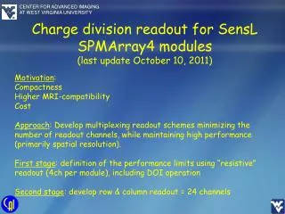
Charge division readout for SensL SPMArray4 modules (last update October 10, 2011) Motivation: Compactness Higher MRI-compatibility Cost Approach: Develop multiplexing readout schemes minimizing the number of readout channels, while maintaining high performance (primarily spatial resolution). First stage: definition of the performance limits using “resistive” readout (4ch per module), including DOI operation Second stage: develop row & column readout = 24 channels
SPMArray4 4ch readout The SPMArray4 module from SensL equipped with resistive 4ch readout from AiT Instruments. The output channels integrated and digitized in the AiT Instruments FPGA DAQ module (not shown). 40ns/div ADC Gate ~125ns
SPMArray4 4ch readout 1.5mm LYSO array 15.4% FWHM @511 keV 15.0% FWHM @511 keV 2.8mm window 15% FWHM 1274 kev/511 kev ratio = 2.51 vs 2.49 expected Raw images, and a profile through one pixel raw, at 511 keV, and examples of energy spectra for a 1.5mm step 10mm thick LYSO array.
SPMArray4 4ch readout 1.0mm LYSO array 13.7% FWHM @511 keV 14.7% FWHM @511 keV 14.7% FWHM 2.8mm window 1.5mm window Raw images, and a profile through one pixel raw, at 511 keV, and examples of energy spectra for a 1mm step 10mm thick LYSO array.
Array4p9 – a compact ~2” PM Array4p9 Array4p9 H8500 1 channel Sum of four 50ns The SiPM based photomultipliers are in principle much more compact than standard PMTs, when implemented with compact electronics. At right is the H8500 flat panel PMT from Hamamatsu with four channel resistive readout. In the center is the Matrix9 module from SensL with all-digital pixel readout of all 144 3mm pixels. At left and at top right is the Array4p9 module from SensL with AiT Instruments resistive 4ch readout. The four output channels (scope picture of one is shown, as well as of the sum signal) are integrated and digitized in the AiT Instruments FPGA DAQ module (not shown).
First Results Array4p9 1.5mm LYSO array 81.1 F 15.6% @511 keV FWHM 16.5% @511 keV FWHM 16.2% @511 keV FWHM 16.5% @511 keV FWHM Image at 511 keV and selected pixel energy spectra, at 81.1 deg F. 22Na source. Proteus LYSO array of 28x28 1.51 x 1.51 x10mm pixels (1.59 mm pitch) was coupled to the Array4p9 module through a 2mm thick acrylic spreader window. Optical coupling grease (Visilox V-788) was applied to all optical surfaces (wet coupling). 15.5% @511 keV FWHM
First Results Array4p9 1.5mm LYSO array 43.2 F Raw image and a profile at 511 keV through one pixel raw, at 42.3 deg F. 22Na source. Proteus LYSO array of 28x28 1.51 x 1.51 x10mm pixels (1.59 mm pitch) was coupled to the Array4p9 module through a 2mm thick acrylic spreader window. Wet coupling. Pixel energy resolution @511 keV measured from 14.5 to 16.8% FWHM, depending on the position of the LYSO pixel in the SiPM array. (Amplitude at this temperature was about 1.6 higher than that at 81.1 deg F, when measured at the same bias voltage.)
Second Array4p9 Module 1.5mm LYSO array ~74 F Array4p9 H8500 1274 keV 511 keV 511 keV Raw images obtained for 1274 keV and 511 keV photopeaks at room temperature (~ 74 deg F) using the second SiPM module and slightly modified readout circuitry. 22Na source. Proteus LYSO array of 28x28 1.51 x 1.51 x 10mm pixels (1.59 mm pitch) was coupled to the Array4p9 module through a 2.15mm thick acrylic spreader window. A comparative measurement was done with the H8500 flat panel PMT using the same LYSO array. Wet coupling. The image at 1274 keV can be used to provide better definition of the crystal map, especially at the edges of the module.
First Array4p9 Module 1.5mm LYSO array 43.2 F 511 keV 1274 keV Raw images obtained for 1274 keV and 511 keV photopeaks at 43.2 deg F using the first SiPM module. 22Na source. Proteus LYSO array of 1.51 x 1.51 x 10mm pixels (1.59 mm pitch) coupled through a 2.15mm thick acrylic spreader window. Wet coupling.
First Array4p9 Module 1.5mm LYSO array ~75 F 511 keV Raw image obtained after final re-optimization at 511 keV and at ~75 deg F. 22Na source. Proteus LYSO array of 1.51 x 1.51 x 10mm pixels (1.59 mm pitch) coupled through a 2.15mm thick acrylic spreader window. Wet coupling.
First Array4p9 Module 2mm LYSO array 43.2 F 17.6% FWHM 16.0% FWHM 511 keV 1274 keV 15.8% FWHM 17.7% FWHM @511 keV Ratio: 2.53 16.4% FWHM Normalized energy for the full detector. Raw images at 511 keV and 1274 keV and energy spectra for selected LYSO pixels as well as normalized energy for the full detector at 43.2 deg F. 22Na source. Proteus LYSO array of 2.0 x 2.0 x 15mm pixels (2.0 mm pitch) coupled through a 2.15mm thick acrylic spreader window. Wet coupling.
First Array4p9 Module 2mm LYSO array array array 80 F 18.5% FWHM 17.5% FWHM 19.2% FWHM 16.1% FWHM 511 keV 1274 keV Raw images at 511 keV and 1274 keV and energy spectra for the four selected LYSO pixels at 80 deg F using the first SiPM module. 22Na source. Proteus LYSO array of 2.0 x 2.0 x 15mm pixels (2.0 mm pitch) coupled through a 2.15mm thick acrylic spreader window. Wet coupling.
Double-Sided Operation Two identical Array4p9 modules with 4ch charge division readout from AiT Instruments were coupled from both ends of a 10x10 1.5mm step 15 mm thick LYSO array from Proteus optimized for DOI operation. Room temperature. Wet coupling through 2mm thick spreader windows. Bias voltages: 29.2 and 29.6 Volt. ADC integration gate: 100 nsec. Out_2 Out_1 All results for one selected 1.5mm LYSO pixel and broad511 keV gamma beam from 22Na. Out_2 Out_1 511 keV energy window 20% 80% Sum 14.2% FWHM DOI=Out_1/Sum Left: Raw image at 511 keV with row projection and energy spectra for the selected LYSO pixel. Both outputs were combined to form ONE image, showing good separation of individual 1.5mm pixels. Both individual energy spectra are broad, as expected, due to the DOI feature of the scintillator array.
Double-Sided Operation Two identical Array4p9 modules with 4ch charge division readout from AiT Instruments were coupled from both ends of a 10x10 1.5mm step 15 mm thick LYSO array from Proteus optimized for DOI operation. Room temperature. Wet coupling through 2mm thick spreader windows. Bias voltages: 29.2 and 29.6 Volt. ADC integration gate: 100 nsec. Out_1 Out_2 Out_2 All results for one selected 1.5mm LYSO pixel and narrow collimated 511 keV gamma beam from a <1mm 22Na source. 21.3% FWHM Out_2 20.7% FWHM Out_1 Out_1 5mm 1.66mm FWHM Sum 16.9% FWHM 20% 80% DOI=Out_1/Sum DOI=Out_1/Sum Left: DOI results at 511 keV and energy spectra for the selected LYSO pixel and a narrow 511 keV gamma beam adjusted to be in the mid-plane of the LYSO array. To calibrate DOI spatial resolution, the beam was moved to two additional and symmetrically placed 5mm spaced positions. Measured spatial resolution includes beam size.
New 4ch charge division readout from AiT 21.2% FWHM 3.11 1 Variant A 2 22.8% FWHM 2.98 511 keV 1274 keV 23.7% FWHM 3.0 1 22.1% FWHM Variant B 3.05 2 23.3% FWHM 2.99 511 keV 1274 keV Operation at 70 F. Bias voltage at 28.8 Volt. ADC signal integration gate of 200 nsec. 1mm pitch Proteus LYSO array of 24x24 LYSO 10mm long pixels. Only about a quarter of the detector populated with the array. The corner region indicated with an arrow. Variant B offers better performance. 1274/ 511 keV Peak ratio
New 4ch charge division readout from AiT 511 keV 19.7% FWHM 2.79 20nsec/div 20.8% FWHM 2.88 Sum pulse shapes with the new 4ch readout (Variant B) 17.7% FWHM 1274 keV 2.76 Operation at 42 F. Bias voltage at 29.5 Volt. ADC signal integration gate of 175 nsec. Proteus 1.0 mm pitch LYSO array of 24x24 10mm long pixels was coupled to the Array4p9 module through a 2.50 mm thick acrylic spreader window using coupling grease. Only about a quarter of the detector populated with the array. 28.8% FWHM 3.47 23.4% FWHM 2.88 1274/ 511 keV peak ratio
New 4ch charge division readout from AiT 17.7% FWHM X 18.9% FWHM 2.54 18.1% FWHM 2.71 23.2% FWHM 3.04 22.5% FWHM 2.94 1274/ 511 keV Peak ratio Operation at 42 F. Bias voltage at 29.5 Volt. ADC signal integration gate of 175 nsec. Proteus LYSO array of 28x28 1.51 x 1.51 x 10mm pixels (1.59 mm pitch) was coupled to the Array4p9 module through a 2.50 mm thick acrylic spreader window using coupling grease. Special thresholding scheme increases the ratio of 1274 keV peak to 511 keV peak (from the 22Na source), as seen at right. Partially this effect is compensated by electronics saturation effects, especially in the edge regions.
New 4ch charge division readout from AiT 21.5% FWHM 0.928 21.5% FWHM 0.98 18.5% FWHM 1.00 23.4% FWHM 0.564 22.3% FWHM 0.705 511 keV Peak ratio Operation at 72 F. Bias voltage at 29.5 Volt. ADC signal integration gate of 175 nsec. Proteus LYSO array of 28x28 1.51 x 1.51 x 10mm pixels (1.59 mm pitch) coupled to the Array4p9 module through a 2.50 mm thick acrylic spreader window using coupling grease.
Row & Column Readout Scheme for the SensL Array4p9 array 19.4% FWHM 2.60 20.8% FWHM R/C: (12 + 12) = 24 ch./144 pixels 2.60 20.5% FWHM 2.68 19.1% FWHM 2.64 1274/ 511 keV Peak ratio Operation at 70 F. Bias voltage at 28.8 Volt. ADC signal integration gate of 150 nsec. Results @ 511 keV. Proteus LYSO array of 28x28 1.51 x 1.51 x 10mm pixels (1.59 mm pitch) was coupled to the Array4p9 module through a 2.50 mm thick acrylic spreader window. Wet (grease) coupling.
Row & Column Readout Scheme for the SensL Array4p9 array 20.2% FWHM 2.81 24.8% FWHM 2.93 R/C: (12 + 12) = 24 ch./144 pixels 29.7% FWHM 2.94 25.2% FWHM 2.94 Corner 23.1% FWHM 2.81 Operation at 70 F. Bias voltage at 28.8 Volt. ADC signal integration gate of 150 nsec. Results @ 511 keV. 24x24 pixel 1mm pitch LYSO array from Proteus. Only about 30% of the detector surface populated with the array. The corner region indicated with an arrow. 1274/ 511 keV Peak ratio
X-Y Readout Schemes for SensL Array4p9 arrays Example: 2x4 array - 72 ch./ ~10cm x 20cm module R/C: (12 + 12) - 24 ch./144 pixel ~ 5cm x 5cm module Example: 4x4 array - 96 ch./ ~20cm x 20cm module (2304 pixels) Example: 2x2 array - 48 ch./ ~10cm x 10cm module
X-Y Readout Schemes for SensL Array4p9 arrays Example: 1x6 array - 84 ch./ ~5cm x 30cm module Example: 2x6 array - 96 ch./ ~10cm x 30cm module
X-Y Readout Schemes for SensL Array4p9 arrays Example: 2x12 (DOI) ring • Readout: • 24 sums for energy and DOI • 12 trigger signals (for coincidence matrix) • position signals - summed both sides – 12x12 outputs/module • multiplexed six modules x 2 = 84 position channels • Total number of position channels = 168 • Total number of readout channels: 192 (for a total of 3456 individual 3mm pixels, reduction factor: 18)
The “resistive” 4ch readout for the SensL SPMArray4 module from AiT Instruments works very well at room temperature (no cooling) down to 1mm LYSO pixel sizes. • The economical, simple and very compact 4ch-per-module readout of the 144 channel Array4p9 module can accommodate the requirements for adequate performance for LYSO scintillation pixel arrays down to ~1.5-2mm pixel size. • The operation is very stable with temperature, with the amplitude change (at the same voltage bias) of less than a factor 2 over the wide tested range of 40-80 deg F. • Initial evidence on DOI operation is that with that design of the readout <2mm FWHM 3D resolution can be obtained using LYSO arrays specially designed for DOI operation. • To achieve 1mm resolution in the present configuration of 3x3 SPMArray4 modules in Array4p9, the row-and-column readout of 12X by 12Y provides this performance at room temperature. • The X and Y outputs from several modules can be multiplexed to produce larger FOV array structures, retaining good spatial resolution, while still with limited total number of ADC readout channels. • Novel 4ch readout from AiT using signal circuitry with signal thresholding is offering better performance than standard “resistive” readout. The optimization of this concept still continues. • Lowering temperature to 42F substantially improves performance. Summary