Download
1 / 23
230 likes | 361 Views
Electronics Design Laboratory Lecture #11, Fall 2014. Experiment 5 Tasks. Final Project Start working on final project ideas Milestone 1, informal discussion about project ideas – November 11 th Nothing due yet… I’ll stop by each lab bench to discuss your ideas. Experiment 5 Specific

E N D
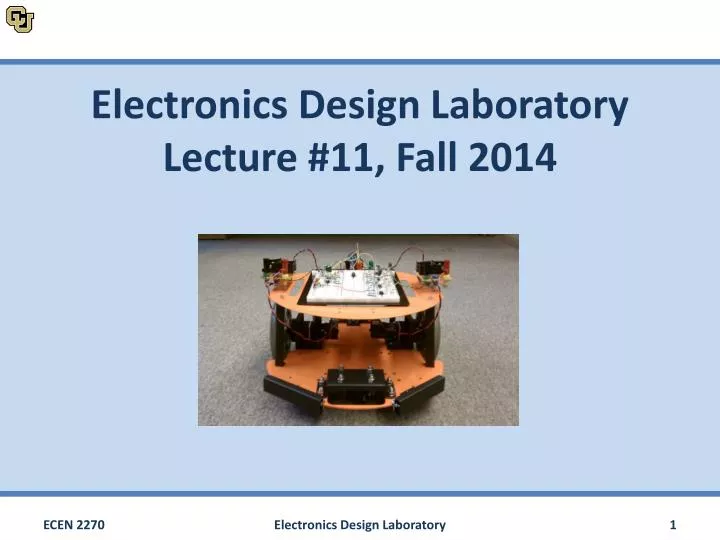
Electronics Design LaboratoryLecture #11, Fall 2014 Electronics Design Laboratory
Experiment 5 Tasks • Final Project • Start working on final project ideas • Milestone 1, informal discussion about project ideas – November 11th • Nothing due yet… I’ll stop by each lab bench to discuss your ideas. • Experiment 5 Specific • Build the components of a wireless on/off and speed control circuit (Part A, 1 week) • Write code for the Arduino to measure the on time of a digital input for speed control (Part B, 1 week) • Demonstrate wireless on/off and speed control of the robot, demo is on November 13th Electronics Design Laboratory
Wireless Transmitter/Receiver • Carrier frequency fc is fixed at 434MHz • Modulation frequency fm is much lower • By filtering vrx the sent data can be re-created Data 1/fm vtx 1/fc RF vrx Data Electronics Design Laboratory
RF Communication Input Signal Modulator Transmitter Receiver Filter Peak Detector Robot (Arduino) • Group A (Red Waveforms) wants to send a 1sec pulse starting at 100ms. Group A will use a 500Hz modulation frequency • Group B (Black Waveforms) wants to send a 1sec pulse as well, but starting at 500ms. Group B will use a 1200Hz modulation frequency • Both groups are going to try and send this signal wirelessly, using a 434MHz wireless transmitter/receiver pair Group A Data Group B Data Electronics Design Laboratory
RF Communication Input Signal Modulator Transmitter Receiver Filter Peak Detector Robot (Arduino) • Both signals are modulated using a 555 timer oscillating at 500Hz for Group A, and 1.2kHz for Group B fm1 = 500Hz Group A Data 5VDC Output Group B Data Input fm2 = 1.2kHz Electronics Design Laboratory
RF Communication Input Signal Modulator Transmitter Receiver Filter Peak Detector Robot (Arduino) • The RF transmitter modulates the signal a second time at the carrier frequency • In this example, a 10kHz carrier frequency is used. The RF transmitters you will be using in the lab transmit at 434MHz fm1 = 500Hz fm2 = 1.2kHz fc = 10kHz Electronics Design Laboratory
RF Communication Input Signal Modulator Transmitter Receiver Filter Peak Detector Robot (Arduino) Group B Transmission RF Noise Group A Transmission • Both RF transmitters are sending on the same frequency • In addition, there is a noticeable amount of noise in most environments • The result is an extremely messy signal, and this is with just two groups transmitting simple pulses. Total RF noise and signal Electronics Design Laboratory
RF Communication Input Signal Modulator Transmitter Receiver Filter Peak Detector Robot (Arduino) • When neither transmitter is operating, the RF spectrum is dominated by noise • This random noise floor is generally of a low magnitude and equally distributed across all frequencies fc Electronics Design Laboratory
RF Communication Input Signal Modulator Transmitter Receiver Filter Peak Detector Robot (Arduino) • When Group A begins to transmit, spikes in the frequency spectrum appear • These spikes are much larger than the noise floor and at known frequencies! fc Electronics Design Laboratory
RF Communication Input Signal Modulator Transmitter Receiver Filter Peak Detector Robot (Arduino) • When Group A begins to transmit, spikes in the frequency spectrum appear • These spikes are much larger than the noise floor and at known frequencies! fc-fm1 fc+fm1 fc Electronics Design Laboratory
RF Communication Input Signal Modulator Transmitter Receiver Filter Peak Detector Robot (Arduino) • When Group B begins to transmit, additional spikes in the frequency spectrum appear • These spikes are at a different frequency than Group A’s transmissions! • Neither signal overlaps with the other fc Electronics Design Laboratory
RF Communication Input Signal Modulator Transmitter Receiver Filter Peak Detector Robot (Arduino) • When Group B begins to transmit, additional spikes in the frequency spectrum appear • These spikes are at a different frequency than Group A’s transmissions! • Neither signal overlaps with the other fc-fm2 fc+fm2 fc Electronics Design Laboratory
RF Communication Input Signal Modulator Transmitter Receiver Filter Peak Detector Robot (Arduino) • When Group B begins to transmit, additional spikes in the frequency spectrum appear • These spikes are at a different frequency than Group A’s transmissions! • Neither signal overlaps with the other fc fc Electronics Design Laboratory
RF Communication Input Signal Modulator Transmitter Receiver Filter Peak Detector Robot (Arduino) • An RF receiver acts as a demodulator • This demodulation shifts the frequency spectrum such that fc = 10kHz is shifted to 0Hz • Both Group A and Group B receivers are picking up everything fm1 fm2 fc fc Electronics Design Laboratory
RF Communication Input Signal Modulator Transmitter Receiver Filter Peak Detector Robot (Arduino) • An RF receiver acts as a demodulator • This demodulation shifts the frequency spectrum such that fc = 10kHz is shifted to 0Hz • Both Group A and Group B receivers are picking up everything fm1 fm2 fc fc Electronics Design Laboratory
RF Communication Input Signal Modulator Transmitter Receiver Filter Peak Detector Robot (Arduino) • Each groups filter is tuned to their specific modulation frequency • This is how we separate our signal from noise and other groups 10nF R3 10nF R1 5VDC Group A Filtered Output 2 3 R2 Group B Filtered Output 5VDC 47kΩ 47kΩ 0.1μF fm1 fm2 Electronics Design Laboratory
RF Communication Input Signal Modulator Transmitter Receiver Filter Peak Detector Robot (Arduino) • Each groups filter is tuned to their specific modulation frequency • This is how we separate our signal from noise and other groups 10nF R3 10nF R1 5VDC Group A Filtered Output 2 3 R2 Group B Filtered Output 5VDC 47kΩ 47kΩ 0.1μF fm1 fm2 Electronics Design Laboratory
RF Communication Input Signal Modulator Transmitter Receiver Filter Peak Detector Robot (Arduino) • Each groups filter is tuned to their specific modulation frequency • This is how we separate our signal from noise and other groups 10nF R3 Group A Filtered Output 10nF R1 5VDC 1 2 R2 5VDC 47kΩ Group B Filtered Output 47kΩ 0.1μF Electronics Design Laboratory
RF Communication Input Signal Modulator Transmitter Receiver Filter Peak Detector Robot (Arduino) • Each groups filter is tuned to their specific modulation frequency • This is how we separate our signal from noise and other groups Group A Filtered Output Group B Filtered Output Electronics Design Laboratory
RF Communication Input Signal Modulator Transmitter Receiver Filter Peak Detector Robot (Arduino) • Peak detector follows the peak value of the waveform • This value is a diode drop less than the real peak! • We can use a comparator on this peak detector output in order to generate our pulse outputs. 0.7V Peak Detector In Out 0.7V Electronics Design Laboratory
RF Communication Input Signal Modulator Transmitter Receiver Filter Peak Detector Robot (Arduino) • Output is time delayed • Output pulses are shorter than input pulses! • There may be ‘bounce’ on positive transitions R3 Peak Detector Comparator 10nF R1 5VDC Input 5VDC R2 Output 5VDC 5VDC 47kΩ R4 R5 47kΩ 0.1μF 0.1μF Electronics Design Laboratory
Project • Must rely on fully functional Lab 2-5 circuits • Can re-do wireless or replace it with a different control method if desired • Your robot does not need a remote control! (ex. line followers and Roombas don’t need remotes) • Must include an additional analog circuit-design hardware component. Programming only add-ons or enhancements do not count. • When selecting components check • Range • Voltage • Communication Electronics Design Laboratory
Sensors Actuators • Your robot • Motors • DC (Brushed or Brushless) • Stepper • Servo • Linear • Solenoid • LEDs • Single Color • RGB w/ PWM control • Infrared • 7 segment • Range • Ultrasonic • Infrared • Buttons • Position • Compass • Accelerometer • Gyros • GPS • Tilt • Sound • Voice Recognition • Microphone • Speakers • Environment • Temperature • Humidity • Altitude • Pressure • Light (LDR, etc) • Physical • Pressure • Flex • Vibration • Buttons • Other • RFID • ZigBee • Bluetooth • Other wireless Arduino • Shields • Motor/Stepper/Servo • GPS • Audio (wave, mp3, etc) • Ethernet • GSM • Wifi • Larger controllers Electronics Design Laboratory