Download
1 / 12
120 likes | 278 Views
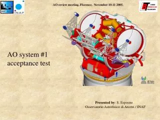
AO system #1 acceptance test. Presented by : S. Esposito Osservatorio Astrofisico di Arcetri / INAF. AO system #1 schedule. WFS alignment with optical test axis. 911mm. W board is assumed to be internally aligned. W board mechanical alignment better than +/-1deg. 1064.7mm. F1.

E N D
AO review meeting, Florence, November 10-11 2005. AO system #1 acceptance test Presented by: S. Esposito Osservatorio Astrofisico di Arcetri / INAF
AO review meeting, Florence, November 10-11 2005. AO system #1 schedule
AO review meeting, Florence, November 10-11 2005. WFS alignment with optical test axis 911mm W board is assumed to be internally aligned. W board mechanical alignment better than +/-1deg 1064.7mm F1 1) Moves stages to focus and center the board to 4D interferometer focus. 2) Measure pupil center rotation when pupil re-rotator Is actuated. [done on a single pupil image]. Maximum pupil displacement will be 8 pixels radius. 3) Unit is shimmed to get center displacement less than 1/10 of a CCD pixel. F/1.22 13713mm F2 F/15.0 BS F1-F2 axis WFS optical axis
AO review meeting, Florence, November 10-11 2005. Pupil registration A fundamental step before starting the process to measure interaction matrices Pupil image having 30 pixels diameter y Quad cell approach to pupil position estimation: Position noise approx. d/sqrt(Nfot) Nfot total number of received photons assume 5e^3 photons/pixel =>3.5e^6 photons 30/sqrt(3.5e^6) = 0.016 pixel d X Centering is repeteable to less than 1/10 of a pixel Important for high order correction
Si=Ti+t*ci Ti Tilt [rad] Tilt [rad] ci AO review meeting, Florence, November 10-11 2005. Sinusoidal modulation technique G. Brusa, On sky closed loop, MMT S. Oberti, On sky open loop fast calibration, VLT
-11/3 -2/3 AO review meeting, Florence, November 10-11 2005. IM calibration The bin size for a 1s demodulation period is 1 Hz Frequency multiplexing allows measurement of more than one mode at a time
AO review meeting, Florence, November 10-11 2005. Lab environment The sinusoidal modulation technique will be useful not only on sky but... ....., in lab and in the solar tower. Not mentioning drifts or non stationary Random processes Sensor signal Time Frequency Placing the sinusoidal scan in a quiet position
AO review meeting, Florence, November 10-11 2005. IM acquisition and system Optimization • IM has to be acquired for: • -3 binnings equivalent to 30x30, 15x15 and 10x10 • -Different modulations, 5-10 values • IM quality test: • -IM symmetry • -Closed loop performance Noise propagation coefficient • Other tests to be done: • -Mode bandwidth and gain optimization • -Statistical reconstructor tests • -IM measurements with injected turbulence (on sky measurements tests)
AO review meeting, Florence, November 10-11 2005. Closed loop acceptance test • No simulated turbulence, full correction (30x30, 1000fps, bright source), slope null for used flat, tech viewer CCD. • no flattening degradation (SR>60, goal 90% @633nm) • temporal stability (20min) • Digital turbulence noise (adding noise commands from LBT672 DSPs), no fitting error, median seeing, IR array. (r0=15cm@500 nm, v_wind=15m/s), H band SR: • 87% with 8mag(R) • 53% with 12mag(R) • 17% with 16mag(R) • MMT phase screens turbulence (same r0 and v_wind), fitting error included • 80% with 8mag(R) • 50% with 12mag(R) • 15% with 16mag(R)
AO review meeting, Florence, November 10-11 2005. Expected performance: SR Test with digital noise Test with MMT screen cromaticity 87 80 K band • Simulate SR has to be • corrected for: • -CCD Read-out time • -RTR computing time • -flat accuracy H band 3x3 53 50 J band 17 Digital Noise SR 1x1 2x2 15 MMT screens
AO review meeting, Florence, November 10-11 2005. Building look up table • SR vs • R0, v_wind (3 seeing conditions) • reference star magnitude (8-17) • Binning mode (3) • Integration time & RON (6,4) • Modes number (easily adjustable) • Tilt modulation (6) Look up tables are the main ingredient for the two AO observing modes that will be presented tomorrow.
AO review meeting, Florence, November 10-11 2005. Conclusion • Schedule allocates 79 working days for complete AO system calibration and acceptance test. No contingency is considered. • New techniques to overcome IM acquisitions with adaptive secondaries is foreseen. It could be applied for on sky measurements. • Building look-up tables process partially included in the schedule • IR test array not yet defined (ARNICA/PISCES…)