Download
1 / 30
300 likes | 350 Views
Explore latest research on particle energies in laser fusion environment for efficient power production. Discover how HiPER bridges laser fusion demonstration to power generation, offering cost-effective solutions. Learn about energy deposition, ion effects on walls, and material challenges in fusion devices. Understand the requirements for electron and ion fast ignition. Investigate diagnostic technologies, heat transport, sputtering, and debris management in fusion environments. Stay updated on proton ignition requirements and advancements in electron transport in laser fusion.

E N D
Particle energies in a laser/fusion environment David Neely1,2,J Collier1, M Dunne1, P McKenna2 and J. M Perlado3 1Central Laser Facility, STFC, Oxfordshire, UK2University of Strathclyde, Glasgow, Scotland 3Instituto de Fusión Nuclear (DENIM)/ETSII/ Universidad Politécnica Madrid, Rutherford Appleton Laboratory, Chilton, Didcot, Oxon, OX11 0QX, UK. Telephone: (44)1235 446150 Fax: (44)1235 445888 e-mail: david.neely@stfc.ac.uk International Conference on Frontiers inDiagnostic Technologies (CFDT1) Frascati, Italy 25-27th November 2009
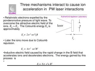
Introduction Fast Ignition and HiPER Electron transport Ion Fast Ignition ? Ultra-high Intensity- “relativistic”
Fast Ignition approach to laser fusion “Fast Ignition” approach of HiPER provides the bridge between laser fusion demonstration (NIF, LMJ) and the route to power production ILE Osaka target picture Ignite the fuel directly using e-beam, ion-beam or KE from multi-PW laser interaction • Significantly smaller (cheaper) capital plant investment • System model predicts cheaper electricity • Allows academia & industry to take lead role • Unique capabilities for a broad science programme
with 18-20 kJ e- 0.9-1.2 g/cm2 range Recent sensitivity modelling (Atzeni, Honrubia et al)
Inertial Fusion Energy distribution Fluka HEAT DEPOSITION IN WALL Energy is deposited in the first mm. Neutrons just deposit around 3% of energy • Atomic particles • Implantation • Sputtering • Debris/Shrapnel SRIM ANSYS Thermo-mechanical response ? • Effect of Ions on wall – Experiments • Pulsed Ion Damage to IFE First- Wall Materials - Lessons for MFE Plasma Facing Materials – • Effect of Ions on wall – Model • We estimated the ablation process using ACORE (Ablation Code for Reactor)- Norimatsu • We estimate the cluster formation/condensation ACONPL - Norimatsu Debris/Shrapnel - Only data available from M. Tobin
Heat deposition with FLAIR • Time dependence Environment and Fusion technology Heat Transport with ANSYS Sputtering with SRIM John Perkins’ calculations ARIES web page HiPER Work Package 8 M Perlado
Neutron first wall damage Characterized by Displacement per Atom (DPA) Typical DPA 10-7 ~ 10-6 DPA / (MJ/m2) For neutron flux energy deposition to ICF Chamber wall: 1.91 x 10³ MJ/m2 Magnetic and Laser Fusion devices face similar material challenges Accumulative DPA < 10-3
Baseline specifications • Implosion energy: • 300 kJ in 5ns • 10 m chamber • 3w? 2. PW beamlines: >70kJ in 10ps 2w (how?) • 3. Parallel development • of IFE building blocks • Target manufacture • DPSSL laser • Reactor designs
Introduction Fast Ignition and HiPER Electron transport in Laser Fusion Ion Fast Ignition ? Ultra-high Intensity- “relativistic”
Fast Ignition requirements Cone enables laser to be delivered within 200 mm of core without interacting with coronal plasma Requirements for energy delivered to pellet: Energy ~15 kJ Spot size ~35 μm Pulse duration <20 ps (hydrodynamic disassembly time) Freeman et al., Fusion Science and Technology, 49, 297 (2006)
e-delivery (Honrubia & Atzeni studies) … • Indicates: • 300 kJ implosion laser • 70 – 100 kJ ignition laser • Assuming • cone to blob ~ 100 mm • divergence ~ 30º half-angle • fl ~ 0.4 mm • code accuracy
Previous experimental work: Target thicknesses ~100 µm Diagnostics: • K emission • XUV emission • Shadowgraphy I = 5 x 10²⁰ W/cm2 Green et al., PRL 100, 015003 (2008) Lancaster et al., PRL 98, 125002 (2007)
Ion emission to diagnose electrons Ion emission: • proportional to high energy ne • proportional to te Ion detector: • Film currently used • Scintillator developments required
Ion emission to diagnose electrons Comparison to other techniques: • CTR: High energy electrons; thin targets • Kα imaging: <100 keV electrons; • Optical probe: Limited accessible plasma density Spatial and energy resolved measurements of the Multi-MeV ions provide a diagnostic of the electron sheath at the target rear surface, and hence the electron transport through the target.
Collimation of fast electron transport Yuan…McKenna., submitted (2009) Evidence of collimation of fast electrons in solid targets by self-generated B-field observed using proton emission
Expected proton energies from simulation Mora 2003 plasma expansion model is used to calculate proton energy using electron density output from LEDA Excellent agreement between simulations (with magnetic field) and experiment
Simulations with 2-D hybrid LEDA code Ne no B field Ne with B field Electron refluxing within thin targets perturbs B-field structure Simulations by Alex Robinson (RAL)
Introduction Fast Ignition and HiPER Electron transport Ion Fast Ignition ? Ultra-high Intensity- “relativistic”
Proton Fast Ignition Requirements: Eprotons (3 to10 MeV) ~15 kJ ELaser ~100 kJ (for ηLaser→proton~15%) ILaser l2~1020 W.cm-2.mm2 tprotons<20 ps Φprotons~35 μm -focusing • How does conversion efficiency scale with laser parameters? • Focusing – need to deliver the energy in a radius ~15 μm • How to prevent preheating of source foil? • Knowledge of ion stopping in plasmas Proton foil Laser Proton foil without re-entrant cone ? M. Roth et al., Phys. Rev. Lett. 86, 436 (2001) M. Temporal, et al., Phys. Plasmas 9, 3098 (2002).
Lateral effects – defocus drive beam Lateral effects dominate when f > tlvhot tef = tl + f/vhot Beam angular profile modified Refluxing increases when f>> (L + ld )
Optimising flux with foil thickness • Vulcan PW 1 ps 1054 nm illumination • Intensity 4x10¹⁹ Wcm-2 • Thinner foils result in • Increased proton flux • As the focal spot size is 60 microns • Lateral spreading is not expected to have a significant effect on electron surface density • Flux loss must be associated with transport losses through foil
Comparison with previous studies • Defocus reduces intensity - proton energy • Defocus enables thin targets – higher efficiency Robson et al, Nature Physics 3, 58 (2007)
Spectral control using multi pulses Grismayer and Mora (PoP 13 032013 2006) showed some spectral modification due to low intensity pre-pulse. What about a high intensity (1018-1019Wcm-2) pre-pulse? Studied this with Vlasov and PIC codes in 1D. ni ni Protons have non-negligible velocity due to first pulse in high intensity case x x vi vi x x Low Intensity pre-pulse High Intensity pre-pulse
Two-stage Mechanism 186μm = rear surf. As the hotter pulse arrives → surge in protons across carbon Front → “wave breaking” + peak in proton density
Integrated dose dual-pulse • Pulse ratio 0.4:1 @ mid1019 Wcm-2 • reduces low energy ~1.2MeV • increases high energies RCF Beam images 1.2MeV 3.2MeV 4.5MeV 5.5MeV Fast Ignition relevant proton energies
Co-workers J Collier, P Foster, R Evans, S Hawkes, A Robinson, M Streeter, C Spindloe, M TolleyCentral Laser Facility, STFC P McKenna, D C CarrollUniversity of StrathclydeF. Nurnberg, M. Roth, M Guentner, K HarresGSI, University of DarmstadtM Zepf, B Dromey, K Markey, S Karr,Queens University of Belfast C-G WahlströmLund Laser Centre, Sweden Y T Li, M H XuBeijing National Laboratory Rutherford Appleton Laboratory, Chilton, Didcot, Oxon, OX11 0QX, UK. Telephone: (44)1235 446150 Fax: (44)1235 445888 e-mail: david.neely@stfc.ac.uk
Conclusion • Ion emission as an electron transport diagnostic • Provides spatial information on hot electron transport • Refluxing effects on many present experiments a limitation • Ion spectral control - dual-pulse and planar • Simple optical control mechanisms- high efficiency • First results indicate mechanism effective • Ion source for probing • Detector developments • Fast Scintillators and transducers required • High resolution neutron and g-ray imaging required • EMP, neutron, g-ray and radiation hardened developments needed
Central Laser Facility Astra Ti:Sapphire 40 fs, 0.5 J Vulcan Nd:Glass 700 fs, 400 J Rutherford Appleton Laboratory (1200 staff) Science and Technology Facilities Council Oxfordshire, U.K.
Dual-pulse timing • Intensity on target mid 1019 Wcm-2 • Lower pre-pulse must come earlier
Proton scaling with defocus • Lower energy protons suited for • Fast Ignition • Secondary heating • Vulcan PW 1 ps 1054 nm illumination • 2 micron think Al targets • Defocus results in • Reduced intensity • Lower maximum proton energy