LCC10 Controller Training, Programming and Application
LCC10 Controller Training, Programming and Application. Rev A – Jan 2011. LCC10 Controller. Agenda Steps in this program: 1. Introduction – Product Specification / Data Sheets / Pin Assignments (Refer to Product Manual and Data Sheet)


LCC10 Controller Training, Programming and Application
E N D
Presentation Transcript
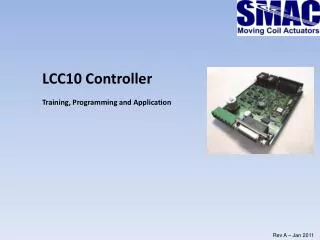
LCC10 Controller Training, Programming and Application Rev A – Jan 2011
LCC10 Controller Agenda Steps in this program: 1. Introduction – Product Specification / Data Sheets / Pin Assignments (Refer to Product Manual and Data Sheet) 2. Introduction – Software and Control options (MotionLab / GUI / HT) 3. Tuning Methods – Use of MotionLab 4. GUI Programming 4.1 Configuration and Setup – Single and Multipole 4.2 Homing 4.3 Position Mode 4.4 Velocity Mode 4.5 Force Mode 4.6 Softland and Measure 4.6 Display Variables 4.7 Digital I/O 4.8 Analogue I/O 4.9 Mathematical functions and comparisons
LCC10 Controller Introduction The LCC10 is the next generation low cost controller solution from SMAC. It provides: • Low cost control solution (List $350, less in OEM qtys) • Single and Multipole (Brushed/Brushless) configuration • RS232 and CANOpen Interface • Digital I/O, Analogue I/O • Servo Performance as per LAC-1 • Interface to any text editor. (HyperTerminal, TeraTerm etc..) • Multiplex RS232 for multi axis systems - Initial Target is to use this controller to cover 80% of existing applications - It will not replace LAC-1 in all applications immediately – fading out rather than replacing.
LCC10 Controller Hardware Configuration – Refer to LCC-10 Product Manual and Data Sheet Key Points: Power Connection – Page 6 Pin 1 = 0V, Pin 2 = + Power (same as LAC-1) 24V to 48V CAN Connection – Page 7 – Jumpers must be in place RS232 Connection – Page 9 - Same as LAC-1, remove jumpers for daisy chain Actuator Connection – Page 13 - Same as LAC-1, uses the same cables. *No dedicated limit switch or coarse home inputs I/O Specification – Page 15 - 5V TTL level I/O 4 In / 4 Out. Note - SMAC will add pull up resistors to Inputs. This give exactly the same operation as LAC-1 Analogue Input – Page 15 & 18 – 0V to 5V, 10 bit resolution. Analogue Output – Page 15 & 19,20 – 0V to 5V 10 bit resolution as standard. – 0V to 10V 16 bit resolution as option (not firmware supported yet)
LCC10 Controller Software……… 3 Methods to communicate with LCC10 • Simple Text Communication – HyperTerminal etc…using the CiA standard command set. • MotionLab – Ingenia Front End 3. SMAC GUI Front End
LCC10 Controller Basic Text Communication The LCC10 uses code based on CiA (CAN in Automation) standards. These consist of CiA301 and CiA402 set of commands. The structure for these commands is industry standard. The commands used by the LCC10 follow this format. Definition The commands are based on variables which are allocated to certain functions within automation. They consist of an Index location (similar to a register) and sometimes a sub index, with a stored value (similar to a register value). There is also a custom set of commands allocated to SMAC. For example position actual value is address 6063, position target is address 6062, mode of operation is address 6060 (to set) and 6061 (to read). These CAN addresses apply to every controller worldwide using this standard. It is also necessary to specify which controller in the network is being addressed each time a command is sent. This due to the multi-node possibilities within the controller network. Each command therefore requires an axis address, a register address and a variable, also it must be specified if a read or write operation is being executed .
LCC10 Controller Basic Text Communication Therefore to read position (equivalent to TP command) the text is as follows: 0x00 r 0x6063 (0x00 = axis address 0, r = read, 0x6063 = actual real position) The response would be 0x20 W 0x6063 180 (180 is the actual position value) ** Unlike LAC-1 it is only possible to send one of these commands at a time to the controller.
LCC10 Controller Example - Force Mode Commands In LAC-1 commands are QM,MN,SQ100 In LCC10 commands are 0x00 w 0x6060 4 (Select Torque Mode – page 59) 0x00 w 0x6040 15 (Select Motor On/Enable ) 0x00 w 0x6071 100 (Set Torque - as Proportion of 1000. Can be negative) And… 0x00 w 0x6040 6 (Motor Off)
LCC10 Controller Example - Position Mode Commands In LAC-1 commands are PM,MN,SA1000,SV100000,SQ10000,MA400,GO In LCC10 commands are 0x00 w 0x60601 (Select profile position mode) 0x00 w 0x6083 150 (Select profile Acceleration) 0x00 w 0x6081 1000 (Select max profile Velocity) 0x00 w 0x6040 15 (Motor Enable) 0x00 w 0x607A 400 (Target Position) 0x00 w 0x6040 63 (Start Motion)
LCC10 Controller Control Word/Status Word/Mode of Operation It can be seen that much use is made of the control word (address 0x6040 (p57)) status word (address 0x6041 p58)), and operating mode (address 0x6060) The control word (read/write) has bit codes which correspond to various states. 0x00 w 0x6040 7 = Switch On 0x00 w 0x6040 0 = Disable voltage 0x00 w 0x6040 6 = Disable Operation The status word (read) has bit codes which correspond to various states. 0x00 r 0x6041 1 = Motor On 0x00 r 0x6041 3 = Fault The Operation Mode word (write) has bit codes which correspond to various states. 0x00 0x6060 1 = Profile Position Mode 0x00 0x6060 3 = Profile Velocity Mode 0x00 0x6060 4 = Profile Torque Mode 0x00 0x6060 6 = Homing Mode
LCC10 Controller Example – PID Constants In LAC-1 commands are SG100,SI100,SD1200 In LCC10 commands are based on an Index and Sub Index memory address. (p114) It is not possible to analyse performance in the text based environment. The Main Index address is 0x2500 (Position Mode) and 0x2501 (Velocity Mode). Sub index address are as follows 1 = Proportional Gain, 2= Integral, 3 = Derivative: 0x00 w 0x12500 100 = Set Position Mode Proportional Gain 0x00 w 0x22500 100 = Set Position Mode Integral Gain 0x00 w 0x32500 1200 = Set Position Mode Derivative Gain 0x00 x 0x12501 = Set Velocity Mode Proportional Gain etc…. The PIDs are based on controller constant parameters internal to the LCC10. There is no direct compatibility with LAC-1 PID parameters.
LCC10 Controller Example – Digital I/O, Analogue I/O (not fully tested) Digital I/O in the LAC-1 commands are CNx, CFx In LCC10 the index address 0x2A02 is used. Sub index 2 is the value of the bit code. Bit 7 6 5 4 3 2 1 0 Value IP4 IP3 IP2 IP1 OP4 OP3 OP2 OP1 Therefore to turn on output 3: 0x00 w 0x22A02 4 To turn off all outputs: 0x00 w 0x22A02 0 To check port status: 0x00 r 0x22A02
LCC10 Controller Example – Digital I/O, Analogue I/O (not tested) Analogue Output in the LAC-1 commands are AL200,WW576,1OM3 Analogue Input in the LAC-1 is GA9,TR In LCC10 the index address 0x2A04 is used (10 bit analogue output). Sub index 2 is the value of the analogue output (p128) Therefore to output 1V (at 10bit): 0x00 w 0x12A04 204 Therefore to output 1V (at 16bit): 0x00 w 0x12A04 13107 To check analogue input (0x2A03) 0x00 r 0x12A03
LCC10 Controller Building a Macro 0x00 w 0x012C05 1 (Macro Number 1) 0x00 w 0x022C05 0 (Command 0) 0x00 w 0x032C05 0x60601 1 (Select Position Mode) 0x00 w 0x022C05 1 (Command 1) 0x00 w 0x032C05 0x60402 15 (Motor Enable) 0x00 w 0x022C05 4 (Command 2) 0x00 w 0x032C05 0x607A4 400 (Set target position 400) 0x00 w 0x022C05 5 (Command 3) 0x00 w 0x032C05 0x60402 63 (Start Motion) However this is not straightforward and the text environment does not allow us to edit easily, troubleshoot or tune the system. As a solution the manufacturer has their own front end software called MotionLab.
LCC10 Controller MotionLAB Ingenia uses a program called MotionLab which is based on their standard controller platform but which is adapted to suit some of the specific SMAC requirements. This allows: • Current Loop Tuning • Velocity Mode Tuning • Position Mode Tuning • Macro Construction • Macro Download / Upload / Edit • It does still require some knowledge of the LCC10 architecture to construct macros and is Ingenia’s standard front end. It is functional but not SMAC intuitive.
LCC10 Controller MotionLAB Refer to Quickstart for MotionLab Live Demo MotionLab In summary the tuning window is useful but the other functions are somewhat limited. Therefore SMAC has developed the SMAC GUI for SMAC actuator specific applications.
LCC10 Controller MotionLAB Startup Window – Select RS232, click next
LCC10 Controller MotionLAB– RS232 port should be identified. Click ‘Go”
LCC10 Controller MotionLAB– device should be found.
LCC10 Controller MotionLAB – Click connect to connect to controller
LCC10 Controller MotionLAB – When asked to upload click yes or no as required
LCC10 Controller Tuning Using MotionLab • For tuning of a brand new unit the Ingenia software Motionlab should be used. The system can be tuned in 3 modes using the controls and graphing feedback within Motionlab. • This tuning guide assumes the actuator and controller system is powered on with RS232 connected and motor enabled (with phase detect completed if using a multi-pole system) • The controller uses 3 PI(D) sets of parameters for each mode. The 3 modes should be tuned in the following order: • 1. Current Loop – This uses Proportional and Integral gain only • 2. Velocity Loop – Again this uses P and I gain only. • 3 Position Loop – Uses P I and D gains.
LCC10 Controller • With Motionlab open and RS232 scanned and connected • 1. Current loop (PI only) • Method: Use Ziegler Nicholls method to tune – increase proportional gain until oscillation is observed, measure the time interval and put into spreadsheet PID.xls or directly into MotionLab calculator • From right side menu click on “Loops” • Click on “Current loop”. Window will display current parameter set. • Click on the small box with 3 dots to adjust. Set all parameters to zero • Set target torque to 100 • Click ‘Download’ • Click ‘Run’ • Increase Proportional Gain in steps of 1000 to 2000 • Repeat until the system becomes unstable and has regular oscillations • Measure the time interval of the oscillation on the graph and put this into spreadsheet PID.xls, or directly into Kposc and Tosc which will then calculate P and I values. • Enter these values into the I loop parameters and re-test to confirm good response. • Click – “SAVE TO NON VOLATILE MEMORY”
LCC10 Controller Current Loop – Parameter Adjustment window Shows start of oscillation – and the calculated Kp and Ki values After this exercise click exit
LCC10 Controller Current Loop After exit Right click on controller Node ID - click save to non-volatile memory
LCC10 Controller • 2. Velocity Loop PI only • Method: Increase the proportional gain until profile is almost achieved but without any overshoot. Then start to increase the integral. • Click on “loops” , Click on “Velocity loop” • Set all parameters to zero • Set target velocity to 50000 • Set target acceleration to 2500000 • Increase Proportional Gain in steps of 10000 to 20000 each time • Click ‘Run’ • Repeat from 1d until profile is ALMOST reached with NO overshoot. • Then start to increase the integral in steps of 100 to 200 each time until profile is achieved. • Exit and Click – “SAVE TO NON VOLATILE MEMORY”
LCC10 Controller • 2. Velocity Loop PI only Shows profile almost reached – no overshoot
LCC10 Controller • 2. Velocity Loop PI only • Increase Integral until profile reached with no overshoot • Exit and save to non volatile memory
LCC10 Controller • 3. Position Loop PID • Method – Set all PID to zero, use the default profile values and Increase Derivative from 100000 in steps of 20000 to 50000 at a time until the profile is almost reached. • Click on “Loops”, Click on “Position loop” • Set all PID parameters to zero • Set Derivative Gain to 50000 • Increase in in steps of 10000 each time • Click ‘Run’ • Repeat until profile is ALMOST reached • Then start with P at 500. • Set acceleration to ACTUAL required values • Click ‘Run’ • Increase the P in steps of 500 upwards until profile is almost achieved. • Then start with Integral but these values are low – start with 5, increase in steps of 5 • **Note that the graph is displaying velocity not position. • Exit and Click – “SAVE TO NON VOLATILE MEMORY”
LCC10 Controller • 3. Position Loop PID • Increase Integral until profile almost reached
LCC10 Controller • 3. Position Loop PID • Adjust P in steps of 500 until close to final profile with no overshoot
LCC10 Controller • 3. Position Loop PID • Increase Integral until profile is well matched
LCC10 Controller SMAC GUI Connect to controller. Open SMAC GUI, select correct port and click “connect to controller”
LCC10 Controller • CAN in Automation (CiA) is the international users' and manufacturers' organization that develops and supports CAN-based higher-layer protocols. • CiA representatives actively support international standardization of CAN protocols and represent the members’ interest in national and international standardization committees, such as ISO and IEC. CiA members initiate and develop specifications that are then published as CiA standards. These specifications cover physical layer definitions as well as application layer and device profile descriptions. • CiA has more than 460 members worldwide. The headquarters is located in Germany. • (From Wikipedia) • Return
LCC10 Controller Velocity Mode Commands In LAC-1 commands are VM,MN,SA1000,SV100000,SQ5000,DI0,GO In LCC10 commands are 0x00 w 0x6060 4 (Select profile velocity mode) 0x00 w 0x6083 150 (Select profile Acceleration) 0x00 w 0x6081 1000 (Select max profile Velocity) 0x00 w 0x6040 15 (Motor Enable) 0x00 w 0x6040 0 (Start Motion)