Comprehensive Guide to Fiber-Based Collocation Architectures
Explore fiber-based collocation architectures with detailed insights into different setups and power sources for CLEC and providers. Direct testimony from Rachel Torrence of Qwest Corporation.

Comprehensive Guide to Fiber-Based Collocation Architectures
E N D
Presentation Transcript
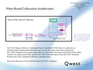
Direct Testimony of Rachel Torrence Qwest Corporation Docket No. 06-049-40 Exhibit RT-1 Page 1 Fiber-Based Collocation Architectures Typical Fiber-Based Collocator Power Source CLEC Collo Fiber Entrance Facility Transition Splice CLEC Provided Fiber Facility Note: For the sake if clarity and simplicity, not all elements along a fiber route have been depicted (i.e. other manholes, distribution Panels, other collocations). C-POI Vault Qwest Wire Center The CLEC brings its fiber to a Collocation Point of Interface (C-POI) where it is spliced to an entrance facility, obtained from Qwest for entry into its wire center, and which extends from the C-POI, through the wire center vault (where it is converted to fire rated central office inside cable), into the wire center central office, and into the CLEC collocation space where the CLEC terminates the fiber onto CLEC equipment within the collocation space. Qwest provides power to the collocation space for CLEC equipment.
Direct Testimony of Rachel Torrence Qwest Corporation Docket No. 06-049-40 Exhibit RT-1 Page 2 Fiber-Based Collocation Architectures Fiber-Based Collocator Using Express Fiber Power Source CLEC Collo Note: For the sake if clarity and simplicity, not all elements along a fiber route have been depicted (i.e. other manholes, distribution Panels, other collocations). CLEC Provided Fiber Facility C-POI Vault Qwest Wire Center The CLEC has brought its own fiber to a Collocation Point of Interface (C-POI) where it hands off a sufficient length of fiber for Qwest to extend it from the C-POI, through the vault and into the CLEC collocation space where CLEC terminates the fiber onto CLEC equipment within the collocation space. (In an express entrance, the fiber entering the vault must be fire rated central office inside cable.) Qwest provides power to the collocation space for CLEC equipment.
Direct Testimony of Rachel Torrence Qwest Corporation Docket No. 06-049-40 Exhibit RT-1 Page 3 Fiber-Based Collocation Architectures Typical Non-Fiber-Based Collocator ( Operating fiber facilities that were obtained from Qwest) Power Source CLEC Collo Fiber Entrance Facility Transition Splice CLEC Fiber Facility Obtained from Qwest C-POI Note: For the sake if clarity and simplicity, not all elements along a fiber route have been depicted (i.e. other manholes, distribution Panels, other collocations). Vault Qwest Wire Center The CLEC obtains fiber from Qwest which extends from the CLEC network to a Collocation Point of Interface (C-POI) where it is spliced to an entrance facility, also obtained from Qwest for entry into its wire center, and extends from the C-POI through the wire center vault (where it is converted to fire rated central office inside cable), into the CLEC collocation space, where the CLEC terminates the fiber onto CLEC equipment within the collocation space. Qwest provides power to the collocation space for CLEC equipment.