Download
1 / 24
240 likes | 259 Views
This paper discusses the cold mass cooling requirements and the design principles to ensure effective cooling using superfluid helium. It presents an overview of the global and local layouts, as well as the main methods of heat extraction and the optimization criteria for maximum heat extraction capacity. The paper also addresses the secondary radial heat extraction and the necessary design features to ensure efficient cooling.

E N D
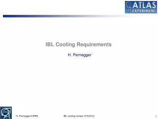
Specific QXF cold-mass requirements to ensure a robust cooling by superfluid helium 4th Joint HiLumi LHC-LARP Annual Meeting: 17-21.11.2014 R. van Weelderen, G. Bozza
Overview Global layout Local layout Main - longitudinal - heat extraction Secondary – radial – extraction 1st evaluation of inner layer quench heaters impact Summary of cold-mass cooling requirements Conclusions
Global Layout (schematic on next slide) The cooling principle is an evolution of the one proposed for the LHC-Phase-I Upgrade: New dedicated refrigerators (placed at the surface) Cold masses cooled in a pressurized static superfluid helium (HeII) bath at 1.3 bar and at a temperature of about 1.9 K – 2.1 K. The heat in the cold masses is conducted through the pressurized HeII to bayonet heat exchangers (HX), protruding the magnet yokes. In these HX's the heat is extracted by vaporization of superfluid helium which travels as a low pressure two-phase flow through them. The low vapour pressure inside the HX's is maintained by a cold compressor system (placed underground), with a suction pressure of 15 mbar, corresponding to a saturation temperature of 1.776 K. The bayonet Hx's can be made to be continuous only through the [quadrupole magnets] or through the [corrector package and dipole].
Global layout (schematic) Schematic architecture of the cooling using superfluid helium
Local Layout (schematic on next slide) The bayonet HX's carry two-phase flow→ they must be in-line throughout the magnets, including their interconnects, that they service. Because of the in-line constraint the HX's circuits are naturally divided between the [Q1, Q2a, Q2b, Q3 & interconnects] and through [CP, D1 & interconnects]. Installation of, internal to the cryostats, phase separators & low-pressure pumping will be slope dependent. The quadrupole HX's need additional pumping, and possible phase separators, at the Q2a-Q2b interconnect.
Local Layout (schematic) schematic placement of external interfaces (QRL-jumpers) over the magnet chain needed for the cryogenic services
Main – longitudinal – heat extraction Optimization (-requirements) for maximum heat extraction capacity (1050 W@7.5x1034 cm2 s-1) giving rise to: Size and # of HX's determined by vapour velocity ≤ 7 m/s (above which the HX's do not function anymore) & the total available heat exchange area, when wetted over their full length. Quadrupole HX's yoke hole size is limited to 77 mm and should not be increased, otherwise one would need to increase as well the overall diameter of the cold mass. ≥ than 2 parallel HX's compromises the interconnects, busbar routing and free conduction areas. An annular space of 1.5 mm between the HX and the yoke to allow contact area of the pressurized superfluid helium on the coil-side. The heat exchangers are to be made of high thermal conductive copper to assure proper heat conduction across the walls. A wall thickness of about 3 mm is required to sustain the external design pressures of 20 bar.
Main – longitudinal – heat extraction The aforementioned optimization leads to: Quadrupoles: • 2 parallel heat exchangers 68 mm ID, yoke holes 77 mm. • Additional low pressure pumping between Q2a and Q2b. • With this configuration about 800 W can be safely extracted. Coping with the remaining 250 W done via active cooling of the other magnets, D1 and CP: D1 & CP: • 2 parallel bayonet heat exchangers of 51 mm ID, yoke holes 60 mm. • With this configuration about 250 W can be safely extracted. Heat must be given some freedom to redistribute along the length of the cold-masses. This is no hard criterion: ≥ 150 cm2through the Q1, Q2a, Q2b, Q3, and their interconnections. ≥ 100 cm2through D1, CP and their interconnections.
Secondary – radial – extraction The Nb3Sn quadrupole coils are fully impregnated, without any helium penetration. The heat loads from the coils and the beam-pipe area can only evacuate to the two heat exchangers by means of the static pressurized HeII. To this end the cold mass design incorporates the necessary radial helium passages.
Secondary – radial – extraction Heat: coil insulation (inner layer quench heaters?) along annular space inner layer-beampipe (here we add heat from beam-pipe as well) through Titanium pole piece through alignment keys around axial rods HX
Secondary – radial – extraction Annular space between cold bore and inner coil block: 1.5 mm Free passage through the Titanium insert and G10-alignment key is given by: “8 mm holes repeated every 50 mm along the length of the magnet”. (The exact repetition rate and size of the radial passages need further refinement in order to find a compromise between the cooling margin obtainable and the mechanical feasibility of integrating these holes.) Freedom to install the 2 heat exchangers in any 2 of the 4 available cooling channel holes in the yoke and to limit asymmetric cooling conditions, some free helium paths interconnecting these 4 cooling channel holes are to be implemented in the cold mass design.
1st evaluation of inner layer quench heaters impact Geometry for the simulations Overall geometry as modelled for OpenFOAM – In green the helium channels E1 = 5670 W/m3 E2 = 3969 W/m3 E3 = 2268 W/m3 E4 = 1134 W/m3 E5 = 567 W/m3 E6 = 226.5 W/m3 Energy deposition map (exaggerated, based on thin tungsten & coil area only) used for the evaluation (will be moved to up to date values in coming weeks)
1st evaluation of inner layer quench heaters impact Geometry for the simulations A photo of the coils 150 μm G10 • 100 μm non-perforated trace (Quench Heaters) of which • 50 μm Kapton • 25 μm stainless steel • 25 μm cyanate ester epoxy 3 x 125 μm Kapton ground insulation 1000 μm G10 500 μm G10 • 100 μm perforated trace (Quench Heaters) of which • 50 μm Kapton (50% surface area) • 25 μm stainless steel (18% surface area) • 25 μm cyanate ester epoxy (36% surface area) Data provided by Paolo Ferracin 150 μm G10 electrical insulation all around each cable 125 μm G10 125 μm G10 250 μm Kapton 150 μm G10
1st evaluation of inner layer quench heaters impact Inner Layer Quench Heaters 100 μm thick Kapton containing a stainless steel resistor, Kapton perforated (perforations end-up filled with epoxy). Photo of perforated-Kapton quench heaters
1st evaluation of inner layer quench heaters impact No Quench Heaters Diametrically opposite cold source heat exchangers 40 mm Holes Spacing Conservative (thin tungsten) luminosity 1.9K cold source heat exchangers Cable temperatures Plot showing where T < 2.17K Iteration temperature probe: the results reached convergence
1st evaluation of inner layer quench heaters impact T current sharing Magnetic field B(T) Courtesy of Susana Izquierdo Bermudez • The lowest Tcs is located in proximity of the winding poles, however we will pay special attention to the mid-plane region which has the highest heat loads (will change according to updated energy deposition maps).
1st evaluation of inner layer quench heaters impact T-margin No Quench Heaters Diametrically opposite cold source heat exchangers 40 mm Holes Spacing Conservative (thin tungsten) luminosity 1.9K cold source heat exchangers
1st evaluation of inner layer quench heaters impact Quench Heaters Diametrically opposite cold source heat exchangers 40 mm Holes Spacing Conservative (thin tungsten) luminosity 1.9K cold source heat exchangers Cable temperatures Plot showing where T < 2.17K
1st evaluation of inner layer quench heaters impact Quench Heaters Diametrically opposite cold source heat exchangers 40 mm Holes Spacing Conservative (thin tungsten) luminosity 1.9K cold source heat exchangers T-margin Whole T range T range up to 6K (most critical zones)
1st evaluation of inner layer quench heaters impact With Without N.B. heat load map conservative (based on thin tungsten, to be up-dated)
Conclusions (1/2) • The requirements to be imposed on the cold mass design to enable cooling the inner triplets by HeII are integrated in the magnet design since the early stage of the design study. • With the present baseline, they fall within the scope of integration in the magnet and cryostat design. • Since very recently we have the completed the (OpenFOAM-based) toolset for calculating heat deposition dependent cooling maps and the resulting T-margin. • Using the toolset it has been conservatively shown that: • T-margin is around 4.2 K (winding-poles) – 5.0K (mid-plane) • Impact of inner layer quench heaters is to lower mid-plane T-margin by ~500 mK and at the winding poles by ~25 mK
Conclusions (2/2) Future plans: Detailed cooling schemes & pipe sizings Evaluation of available global heat extraction margins with the aforementioned cold-mass sizing and cold-source T at 2.1 K. Inclusion of cross-channel connections Finalization of heat-load induced T-maps and T-margins wrt heat-load maps based on thick Tungsten absorbers Evaluation of weak points in the radial extraction path Extension to D1 (+ Follow-up of beam-screen cooling @ 40 K – 60 K, Transients ….)