Download
1 / 19
190 likes | 345 Views
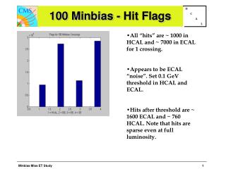
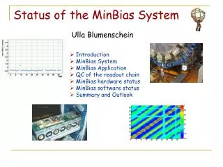
Status of the MinBias System. Ulla Blumenschein. Introduction MinBias System MinBias Application QC of the readout chain MinBias hardware status MinBias software status Summary and Outlook. fiber. Tile Calorimeter. EBA. LBA.

E N D
Status of the MinBias System Ulla Blumenschein • Introduction • MinBias System • MinBias Application • QC of the readout chain • MinBias hardware status • MinBias software status • Summary and Outlook
fiber Tile Calorimeter EBA LBA • Barrel part (h < 1.7) of the ATLAS Hadron Calorimeter • Sampling calorimeter: iron/scintillating plates (tiles), perpendicular to beam axis • Tiles grouped to readout units (cells): 73 cells per Df= 0.1 arranged in projective towers with Dh = 0.1 • 3 layers: A/BC/D • each tile read-out by two PMTs LBC EBC PMT FE electronics tiles cell
DC Calibrations, Luminosity Monitoring The TileCal Readout Cesium In-situ Physics Tile Minimum Bias TileCal cell Fibre Laser Mixer HV PMT PMT Block HV Micro HV Opto Canbus Divider Charge Injection 3-in-1 L H Mother Board Digitizer Analog Integrator ADC-I Canbus Adder Digital Drawer Optical Interface TTC ROD Had Trigger µ Trigger Energy
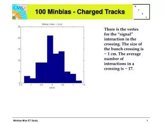
Example of the energy deposition by min.bias events per collision in a given TileCal cell (MC) A1 Tile MinBias Mean energy deposition : O(MeV) • ~ 23 inelastic p-p interactions per BC (900 M int./sec) at nominal lumi • Typically low-energy forward jets (few hard interactions -> “physics”) • Large fluctuation of energy deposition in a given cell • Average MinBias signal spans a broad range of frequencies and amplitude depending on lumi/h/layer • Slow integration of PMT current (10ms ~ 110 LHC orbits ~400000 BC ~8 M inelastic interactions) • readout rate ~ 0.5 Hz • Monitor each cell/PMT channel) online • Store data offline for reference (COOL database) • rLuminosity measurement least exposed to MinBias most exposed to MinBias
TileCAL Luminosity measurement • Physics requirements: average inst. luminosity per lumi block: O(1 min) • ATLAS goal: accuracy of 2% • Absolute Lumi measurement: Roman Pods (elastic cross section) for low luminosities (~1028/cm2/sec) • Relative luminosity measurement, calibrated at low luminosity with Roman Pods in special runs. Online (luminosity monitoring) and offline (analysis) application • - LUCID: delayed, not sure if ready at startup • - alternative methods: W/Z, LAr Forward Calorimeter, MinBias counter, TileCAL ... • TileCAL relative lumi measurement: high accuracy: DL/L < 1% at nominal lumi 1034 with single readout • More difficult: calibration with Roman Pots at 1028 for absolute luminosity measurement: combine several cells, average over lumi block, increase bandwidth by reading only selected cells • Important: negligible electronics noise Lumi Calibration Luminosity X 1034 A13 D0 Stat accuracy (%) of a single measurement as a function of luminosity BC5 Acc (%)
Barrel Extended Barrel MinBias System monitoring DCS (PVSS) data base Lumi monitoring TileCAL monitoring COOL ROB ROB ROB ROB extracted data SBC SBC SBC SBC TDAQ Complete data 20 kbyte/sec
The integrator readout path ATLAS cavern USA 15 INTG_OUT PMT INTG_GND 16 message buffers per CAN line 250 kbps 1 ADC per module 16 ADCs per CAN line) 12 bit digitizer (0-5V) PMT PMT ROB SBC Pedestal Control CAN Port 45(36) PMT channels per module in Barrel (EB) Micro Analog Bus DAC CAN Port ADC CAN Port CAN Port CANBus CAN Port ADC + gains dynamic range: -> ~2 mA
MinBias Hardware Status • Final 15 V ADC Canbus PS installed • Canbus connected to the final ROB in the TileRack. [Connections to the drawers might be modified because of HV readout problems.] • Final ROB and SBCs commissioned. So far still using mobidaq but able to switch to final ROBs/TTCvi any time as soon as digitized readout moves to RODs. • FE components (Integrator, ADC) commissioned for 16 barrel modules (Sector 13). (One pending repair request). Components on the remaining modules certified with mobile readout (mobidick). • Calibration/Monitoring Trigger board (SHAFT board) under construction (IFAE) -> has to be tested in summer
QC software for Integrator/ADC/ROB DVS gui Pedestal distributions • ROB functionalities: receive/send data, trigger, mask buffers ... • ADC functionalities: ADC-CANbus communication, ADC settings, Automated Scan (tests), Fast Dump (MinBias), 3in1 card settings ... • Integrator pedestals: dead/noisy channels, channel-by-channel coherence, stability in time (analysed offline) • Light leak test: fast integrator pedestals in order to check for lightleaks/leakage currents of PMTs upon turnon of the HV • Integrator gains: gain switches (6 gains), linearity, calibration constants
Gains calibration • Uses a charge injection scan (100 events per point, 11 points per gain) to calibrate the 6 gains • Checks routinely for different, more trivial sources of failures (cards not switched, pedestals not in correct range ...) • Precission: 10e-5 • Stable in time (order of hours tested so far) within the precission of the measurement Verify card selection Slope, chi2, pedestal, noise for each gain
Gains test: QC application • Gains test integrated in DVS and part of the QC procedure • Check linearity of the gains and functionality of the gain switches • Overview of the noise for each gain • Check if 3in1 cards are selected properly • Check the charge injection system independently from the digitized readout -> diagnosis of a 3in1 card problem Damaged gain switch (card 40) Damaged charge injection system
Gains calibration: ToDo list • Precission of the measurement is large enough to resolve systematic effects in the CIS system and the ADC -> apply corrections (and switch to laser system once it is available ?) • Check compatibility of different readout methods (CONVERT (MinBias) <-> Automated Scan (calibration) • Check for long-term stability (order of weeks/months) Fit of the gains Residuals (large precission)
~ day of data taking Noise problems • In the integrator pedestal data taken with the final Finger Low Voltage Power Supplies (FLVPS) the pedestal noise in average 4 times larger than with commercial temporary power suppies used in the test beam. Consequences for MinBias Readout: - Tile luminosity cannot be calibrated - up to 15 X more time for same accuracy Typical noise with Linear LVPS (LBA47) Noise with Finger LVPS (LBA51)
Noise problems • Channel-by-channel coherence pattern suggested a dominant source in the 500 Hz range: Bricks with low load run in discontinuous mode -> voltage oszillations Channel-by-channel correlation pattern in (LBA50) Lower noise level with temporary noise reduction in LBA48 <-2ms-> • Temporary fix: resistance in parallel to the module and capacitance • Final fix: modify bricks (several months)
The MinBias Software TDAQ tools DVS Tile VME boards Configuration ROB library Run Start MinBias library IADC library DVS QC Monitor TTC library Transfer to DCS/COOL Data base access
MinBias Software Status • C++ libraries with methods for VME-based operation of front end electronics have been developed/extended • QC procedures for front end and back end electronics which use the new libraries developed/extended and applied successfully in commissioning • Developed calibration tool for the 6 gains of the integrator electronics -> calibration constants, transferred to COOL data base • Developed C++ MinBias library which contains all MinBias TDAQ methods following Ilyas C-based MinBias software • Stand-alone DAQ tools for configuration, running and retrieving of the data (to be included into TDAQ framework in summer) • Addidional temporary methods for commissioning purpose (different readout methods, timing measurements, switch backends: mobidaq/final ...) • Performance checks of MinBias software with 4 modules in parallel (largest number available so far with fixed FLVPS): Comparison with DVS readout (single module), stability, data rate
Pedestal data (run 4 modules in parallel) All PS with temporary noise killers • Use pedestal data to validate the MinBias readout • Characteristic quantity: Channel-by-channel pedestal RMS LBA45 LBA46 LBA48 LBA47 • Reference: Well established single-module test-readout (Automated Scan) • Trigger: ROB, ~95 Hz LBA45 LBA46 LBA47 LBA48
Different Readout procedures LBA46: MinBias run (CONVERT) Reference: Single-module automated scan run LBA46: MinBias run (FASTDUMP) Reference: Single-module automated scan run
Outlook • Integrate the stand-alone tools into TDAQ framework and check for incompatibilities in configuration. • Integrate the readout into DCS • Tool for data storage COOL data base • Check timing in detail and try to increase performance further • Test details (algorythm for cycling 16 ADCs at 15 data buffers, long-term stability of readout, handling of bad channels/modules ...) • More advanced commissioning status needed for further MinBias development: - full CAN line (daisy chain, 16 modules) instrumented and certified - stability at the timescale of days - enough time slots for tests (no high-priority problem handling)