Download
1 / 66
660 likes | 679 Views
Learn how to modify 3D geometry using Thin/Surface, Fixed-Radius Blend, Variable Radius Blend, and Chamfer features in this detailed workshop guide. Understand how to create thin solids, optimize blending, and achieve smooth transitions effortlessly. Advance your skills with practical examples and expert tips.

E N D
Chapter 5 Advanced 3D GeometryModifying Geometry, Advanced Features and Body Operations
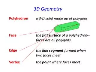
Modifying 3D Geometry 3D Curve Feature Planar Bodies Named Selection Base Objects Pattern Feature Advance Features Advanced Tools Body Operations Workshop 5-1, Enclosure Operation Workshop 5-2, Pattern Operation Workshop 5-3, 3D Curve 3D GeometryContents December 17, 2004 Inventory #002176 5-2
3D GeometryModifying 3D Geometry • Thin/Surface : • The Thin/Surface feature has two distinct applications: • Create thin solids (Thin). • Create simplified shelling (Surface). • Selections available from Details: • Faces to Remove: selected faces will be removed from their bodies. • Faces to Keep: selected faces will be kept, while unselected faces are removed. • Bodies Only: the operation will be performed on the selected bodies without removing any faces. • When converting solids into thin solids or surfaces you can specify a model's thickness in one of three offset directions: • Inward • Outward • Mid-Plane December 17, 2004 Inventory #002176 5-3
3D GeometryModifying 3D Geometry… • Thin/Surface details: Basic operation Direction for thin solid or offset Thickness or Thickness/Face Offset IMPORTANT! To create surface geometry (NOT thin solids) the Thickness field must be set to zero (0). Examples . . . December 17, 2004 Inventory #002176 5-4
3D GeometryModifying 3D Geometry… • Using the simple block shown here let’s look at basic Thin/Surface behavior. December 17, 2004 Inventory #002176 5-5
3D GeometryModifying 3D Geometry… • After generating the feature notice: • The end face is removed • Thickness = 2 mm • Direction is toward original solid’s center (inward) • Result is still a solid • By changing the thickness field to zero and re-generating: • True surface model results December 17, 2004 Inventory #002176 5-6
3D GeometryModifying 3D Geometry… • Notes on Thin/Surface: • The Thin/Surface feature supports thickness > 0 if the selected faces are part of surface bodies. • This allows for the “thickening” of an imported surface. • Mid Plane Option: • This does not mean midplane extraction. • Bodies will be hollowed, such that the inner and outer walls of the bodies are offset equal distances from the original faces. • Example : Resulting offset is in both directions. Solid body selected for Thin/Surface midplane December 17, 2004 Inventory #002176 5-7
3D GeometryModifying 3D Geometry… • Fixed Radius Blend: • The Fixed-Radius feature allows you to create blends on model edges. • You can select or preselect 3D edges and/or faces for blending. • Face selection applies blend to all the edges from that face. • When preselecting, additional options are available from a RMB context menu (face edge loop selection, smooth 3D edge chain) • You can edit the blend radius in the Detail View. Clicking Generate completes the feature creation and updates the model. • Variable Radius Blend (same as above plus): • Use the Detail View to change the start and end blend radius for each edge. Also, the Detail View can set the transition between blends to smooth or linear. Clicking Generate completes the feature creation and updates the model. • Examples . . . December 17, 2004 Inventory #002176 5-8
3D GeometryModifying 3D Geometry… Face selected for fixed blend. All edges receive blend Details specify blend radius Edges selected for fixed blend. December 17, 2004 Inventory #002176 5-9
3D GeometryModifying 3D Geometry… Linear Transition Smooth Transition Variable radius blend If multiple edges selected for VR blend each is listed in Detail December 17, 2004 Inventory #002176 5-10
3D GeometryModifying 3D Geometry… • Chamfer: • The Chamfer feature allows you to create planar transitions (or chamfer face) across model edges. • You can select or preselect 3D edges and/or faces for chamfering. • If a face is selected, all the edges from that face are chamfered. • When preselecting, additional options are available from a right mouse button context menu (face edge loop selection, smooth 3D edge chain) • Every edge on a face has a direction. This direction defines a right and left side. • Chamfer is defined either by two distances from the edge for the planar transition (chamfer face), or by a distance (left or right) and an angle. • The type of chamfer is set up in the Detail View along with the distances and angle. • Examples . . . December 17, 2004 Inventory #002176 5-11
3D GeometryModifying 3D Geometry… Chamfer options (3): Left Right December 17, 2004 Inventory #002176 5-12
3D Geometry 3D Curve Feature • >Concept>3D Curve • 3D Curves can be used for: • Custom curves for Concept Modeling • Base Object in Modeling a Feature • Create 3D curves (Line Bodies) from: • Existing Model points • Coordinates (text) File • Curve passes thru all points in the chain. • All points must be “unique” • Curves may be either open or closed. Closed Curve Open Curve December 17, 2004 Inventory #002176 5-13
3D Geometry3D Curve Feature -Existing Points • >Definition>Point Select • Select (and >Apply) existing model points • Hold <CTRL> key to select multiple points. • Curves may be either open or closed. (RMB) • Resulting curve passes thru all selected points. RMB December 17, 2004 Inventory #002176 5-14
3D Geometry 3D Curve Feature - Point File Method • >Definition>From Coordinates File • 3D curve created by XYZ coordinates in a text file. • Format of Coordinates (text) File • # indicates Line is a comment • Empty lines are ignored • A data line consists of 5 fields, separated by spaces or tabs A) Group # (integer) B) Point Number (integer) C) X coordinate D) Y coordinate E) Z Coordinate • Notes: • A data line with the same group# and Point# is in error. Must be unique • For a closed curve, the point number of last line should be zero. • Coordinate fields ignored. #Group 2, closed curve example file #A B C D E 2 1 100.0101 200.2021 15.1515 2 2 -12.3456 .8765 -.9876 2 3 11.1234 12.4321 13.5678 2 0 Example: SineCurve xyz data points December 17, 2004 Inventory #002176 5-15
3D Geometry Planar Bodies • Planar bodies are surface bodies in the XY-plane. • Planar bodies created in DM are used to perform 2D Sim. • Plane Strain, Plane Stress, Axisymmetry • Numerically more efficient Sim models compared to “full” 3D models. Solid Planer December 17, 2004 Inventory #002176 5-16
3D Geometry Named Selection Base Objects • Named Selections can be used as base objects (Groups) for basic modeling features. • The named selection may contain either Bodies, Faces, Edges, or Points. • Named Selections may be transferred to Sim • must be selected in “Default Geometry Options” in environment Project Page or used in the creation of some features. December 17, 2004 Inventory #002176 5-17
Pattern feature allows you to create copies of faces or bodies in: Linear (direction + offset distance) Circular (rotation axis + angle) Can set angle=zero to get auto-calculated evenly spaced instances Rectangular (two sets of directions + offsets) For face selections, each copied instance must remain coincident with the originating body (must touch same base region). Each copied face incidence must not touch/intersect each other 3D Geometry Pattern Feature Linear Circular Rectangular December 17, 2004 Inventory #002176 5-18
Easy to change the “Copies” (in Details) and “>Generate”. Total # = “Copies” + 1 3D Geometry Pattern “Copies” 5 9 December 17, 2004 Inventory #002176 5-19
3D GeometryAdvanced Features • Two Advanced Feature Properties described in this section apply selectively to the 3D Features: • Target Bodies: Extrude, Revolve, Sweep, Skin/Loft, Slice, Import & Attach. • Merge Topology: Extrude, Revolve, Sweep, & Skin/Loft. • Target Bodies: allows users to specify which bodies are operated on during a Cut, Imprint, or Slice operation. • By switching the value of the Target Bodies property from “All Bodies” to “Selected Bodies”, the user can select bodies through another Apply/Cancel property called Bodies. Cut operation applied only to Selected Bodies December 17, 2004 Inventory #002176 5-20
3D GeometryAdvanced Features… • Merge Topology Detail property for Extrude, Revolve, Sweep, & Skin • A Yes/No detail option that gives control over feature topology. >Yes: optimizes the topology of feature bodies. >No: leaves the topology of feature bodies unaltered. • The default setting for Merge Topology differs depending on the 3D feature you are using: • Extrude: default is Yes • Revolve: default is Yes • Skin/Loft: default is No • Sweep: default is No • Example follows . . . • Note: In version 7.0 and earlier Merge Topology is a read-only property whose behavior is, inner profile faces are merged but outer profile faces are not. This means that features created in 7.0 and older versions cannot be changed December 17, 2004 Inventory #002176 5-21
3D GeometryAdvanced Features… Topological Control Merge Topology = >Yes Merge Topology = >No • Setting the value to >Yes optimizes all topology of the feature body. It is however, recommended to leave this setting as >No (default) for the Skin/Loft and Sweep features. • Use caution when changing the value of the Merge Topology property. • Once other features depend on this, faces and edges may appear or disappear and cause failures and invalid selections for subsequent features. December 17, 2004 Inventory #002176 5-22
3D GeometryAdvanced Tools • Advanced operations are available via the >Create and >Tools Menu: • Freeze • Unfreeze • Named Selection • Joint • Enclosure • Fill • Surface Extension • Winding Tool • Pattern • Body Operation • Slice • Face Delete December 17, 2004 Inventory #002176 5-23
3D GeometryAdvanced Tools… • Normally, a 3D solid feature operates like this: • Create the bodies of the 3D feature (e.g., an Extrude feature) • Merge the feature bodies with the existing model via Boolean operations: Add Material, Cut Material, Imprint Faces • The Freeze feature allows you to control the second step acting as a separator in the construction history as displayed in the Feature Tree. • Bodies created from features before a Freeze will become frozen • Frozen bodies are denoted by the ice cube icon next to the body’s branch of the Feature Tree • All frozen bodies are ignored by Add, Cut, or Imprint Material operation for any features following the Freeze • An example . . . December 17, 2004 Inventory #002176 5-24
Second extrusion is independent solid. Without the freeze this geometry would have been merged with the import 2 existing solids now frozen 3D GeometryAdvanced Tools… Modeling history: Model began with imported geometry. An extrusion was added A freeze was inserted A second extrusion was created adjacent to the imported geometry Frozen Unfrozen December 17, 2004 Inventory #002176 5-25
3D GeometryAdvanced Tools… • Unfreeze allows one to selectively “remove” the freeze from single or multiple bodies (freeze is a global operation) • Assembly notes: • By default if you import an assembly from a CAD package the assembly will remain as separate parts in DM without freezing • Any subsequent 3D modeling operation however will result in a merge of any touching bodies in the assembly • This can be avoided with the Freeze and Unfreeze tools December 17, 2004 Inventory #002176 5-26
3D GeometryAdvanced Tools… • Named Selections: • Can group entities under a single name • Group can be transferred to Simulation DesignModeler Simulation Note, DM allows different entity types to be grouped (points, edges, surfaces), whereas Simulation does NOT. Simulation will split non-homogenous groups. December 17, 2004 Inventory #002176 5-27
3D GeometryAdvanced Tools… • Joint Feature: • Joins surface bodies together (for proper treatment in Simulation) • Active or frozen bodies are eligible • Topology can be shared (common mesh) or not (contact region) • Example: Surface model consists of 3 surface bodies. Edges along 2 bodies contact faces on the third. Without the joint feature, in Sim the mesh would be discontinuous at the interface (no nodal match up). December 17, 2004 Inventory #002176 5-28
3D GeometryAdvanced Tools… • Using the share topology “>Yes” (default) the mesh along the boundary in Simulation is continuous • Using share topology “>No” allows the edge/surface boundary to be modeled using contact elements (note face/edge detection must be set to “>Yes”) December 17, 2004 Inventory #002176 5-29
3D GeometryAdvanced Tools… • Enclosure: • Creates surrounding region around bodies to facilitate simulation of field regions • CFD, EMAG, etc • Box, sphere, cylinder or user defined shapes can be employed • Cushion property allows the boundary extent to be specified (must be > 0) • Apply enclosure to all bodies or only selected targets • Merge property allows for automatic multi-body part creation • Ensures original part and enclosure will have nodal match up when meshed December 17, 2004 Inventory #002176 5-30
3D GeometryAdvanced Tools… • Example: Circuit board model Cutaway view of enclosure Enclosure created using box option December 17, 2004 Inventory #002176 5-31
3D GeometryAdvanced Tools… • Fill: • Creates frozen bodies that fill interior voids such as holes • Works with active or frozen bodies • Works only with solid bodies • Useful for numerous CFD applications • Example: Goal is to model the interior (fluid region) of the valve block shown here The desired (37) interior faces are selected then the Fill is inserted December 17, 2004 Inventory #002176 5-32
3D GeometryAdvanced Tools… • Example (cont.): Resulting fill is frozen (meshable) body Interior region, now isolated, can be taken to Simulation for meshing December 17, 2004 Inventory #002176 5-33
3D GeometryAdvanced Tools… • Winding Tool, for use with ANSYS Workbench - EMAG • Creates a Winding Body (a special Line Body) • Represents loops of wire, for instance, wire wound thru a rotor or stator • First create a model of rotor or stator including the center plane that defines the alignment of the winding bodies. Line Bodies are automatically named using phase & coil from the winding table. December 17, 2004 Inventory #002176 5-34
3D GeometryAdvanced Tools… • Then use “Winding Tool” to open the Winding Table file: • Winding Table is a text file. • The Line Bodies are automatically named using phase & coil from a winding table. • Winding Tool is fully covered in ANSYS Workbench - Emag Course Example Winding Table Resulting Line Bodies December 17, 2004 Inventory #002176 5-35
3D GeometryAdvanced Tools… • Surface Extension: • Creates a surface extension based on edge selection • Extension can be fixed or to selected faces • Example: A thin solid model is converted to a mid plane surface model The result is a gap at the intersection of the 2 parts Extending the circular edge closes the gap December 17, 2004 Inventory #002176 5-36
After “Face Delete” the result is no blends, cavities or holes Select the highlighted surfaces 3D GeometryAdvanced Tools… • Face Delete: • Can remove features such as blends and cuts by removing faces from the model - - then heal the resulting “wound” • If a suitable extension cannot be determined, the feature will report an error stating that it cannot heal the wound • Used to defeature (simplify) imported models (e.g. remove a hole) • If desired the hole could be recreated in DM to parameterize it Example (delete blends and hole feature): December 17, 2004 Inventory #002176 5-37
3D GeometryAdvanced Tools… • Slice feature: • Slice is only available when the model consists entirely of frozen bodies • Slice has two options: • Slice By Plane: Select a plane and the model is sliced by this plane • Slice Off Faces: Select faces on the model and DM will “slice off” these faces then attempt to create a separate body from them Result is 3 solids. Each blend becomes solid region Original geometry, one solid 2 blends chosen for slice December 17, 2004 Inventory #002176 5-38
3D GeometryAdvanced Tools… • Slice by Plane example: • Original imported Parasolid geometry (typically) does not lend itself to mapped (sweep) meshing in Simulation Resulting FE mesh = all tets Imported geometry in DM 1 Body December 17, 2004 Inventory #002176 5-39
3D GeometryAdvanced Tools… • Use Slice operation to divide body into 4 bodies (single Part) Original (frozen) geometry is divided via 2 Slice operations Result: 3 bodies (Brick) swept meshed for Sim 1 body tet mesh December 17, 2004 Inventory #002176 5-40
3D GeometryBody Operations • Body Operation: allows users to manipulate bodies via 8 different options (not all will be available at all times): • Any type of body can be used with Body Operations, (active or frozen). • Point Feature points, attached to the faces or edges of the selected bodies, are not affected by the Body Operation • Bodies and Planes are selected via the Details View • Options include: Mirror, Move, Copy, Delete, Scale, Cut Material, Imprint Faces, & Slice Faces. • Each described next . . . December 17, 2004 Inventory #002176 5-41
3D GeometryBody Operations… • Mirror: • User selects bodies and a mirror plane. • DM creates copies of the selected bodies that are reflections of the original bodies in the mirror plane. • Active bodies that are reflected will be merged with the active model. • Frozen bodies that are reflected will not be merged. • By default, the mirror plane is initially the active plane. • Example: selected surface here is mirror plane. December 17, 2004 Inventory #002176 5-42
3D GeometryBody Operations… • Move: • Users select bodies and two planes: a source plane and a destination plane. • DesignModeler will transform the selected bodies from the source plane to the destination plane. • This is especially useful for aligning imported or attached bodies. • Example: • Two imported bodies (a box and a lid) don’t align. • Maybe they were exported separately from a CAD system in two different coordinate systems. • Problem is corrected in “>Move” Body Operation. 1 2 1,2 December 17, 2004 Inventory #002176 5-43
3D GeometryBody Operations… • Copy: same as the Move operation except that copies of the bodies are moved while the original bodies remain unaltered. • Delete: users select bodies to delete from the model. • Scale: users select bodies to scale, then select a scaling origin through the Scaling Origin property. • This property is a combination box with three options: • World Origin: The origin of the global coordinate system is used. • Body Centroids: Each body is scaled about its own centroid. • Point: User can select a specific point, (2D sketch point, 3D vertex, or PF Point) to use as the scaling origin. December 17, 2004 Inventory #002176 5-44
3D GeometryBody Operations… • Cut Material: • Users select bodies for a cut operation from the active bodies in the model. • Body Operation's Cut Material option works the same way as Cut Material does for any of the basic features. • Example: • Airplane body is selected to cut from the block to form a mold: December 17, 2004 Inventory #002176 5-45
3D GeometryBody Operations… • Imprint Faces: • Body Operation's Imprint Faces option works the same way as Imprint Faces does for any of the basic features. • This option is available when active bodies exist in the model. • In this example, the selected body is used to imprint the faces of the block: December 17, 2004 Inventory #002176 5-46
3D GeometryBody Operations… • Slice Material: • Slice operations are performed on a completely frozen model. • Body Operation's Slice Material operation works the same as Slice Material does for any of the basic features. • Option is available only when all bodies in the model are frozen. • Example of a slice operation: airplane body is selected to slice the block: December 17, 2004 Inventory #002176 5-47
Workshop 5-1, Enclosure Operation • Goals: • Import a model in Parasolid format • Use the enclosure operation to create a solid region representing the model’s surrounding field December 17, 2004 Inventory #002176 5-48
Workshop 5-1, Enclosure Operation • Start Page: • Choose the “Geometry” icon to start a new DM session or >File>New • When prompted select “meter” as the length unit December 17, 2004 Inventory #002176 5-49
1 2 Workshop 5-1, Enclosure Operation Import the Parasolids file “blade.x_t”. • [Main menu] >File> Import External Geometry File . . . Browse to file “blade.x_t” and open. • “>Generate” the import. December 17, 2004 Inventory #002176 5-50