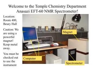
EMMA Magnet
EMMA Magnet. Neil Marks ASTeC Cockcroft Institute ‘All-hands’ meeting; 29 March 2007. Acknowledgements:. With considerable thanks to: Ben Shepherd; Take Yokoi (Adams Institute); Neil Bliss; Clive Hill,

EMMA Magnet
E N D
Presentation Transcript
EMMA Magnet Neil Marks ASTeC Cockcroft Institute ‘All-hands’ meeting; 29 March 2007
Acknowledgements: With considerable thanks to: Ben Shepherd; Take Yokoi (Adams Institute); Neil Bliss; Clive Hill, (who have done most of the work and produced most of the material that you are about to see).
EMMA Magnets – ‘Unusual Features’ • magnets provide both dipole (bending) and quadrupole (focusing) field – they are ‘combined function’ magnets; • the quadrupole field is far stronger than the dipole field – they are therefore displaced quadrupoles; • independent adjustment of the dipole and quadrupole field is required; • they are very short – yoke lengths of 55mm and 65mm – of the same order as the inscribed radius – ‘all ends and no middle’.
Modelling carried out with CST EM Studio (3D code) F magnet D magnet now with ‘realistic’ steel –details provided by Tesla Combined model http://www.cst.com/
Field Clamps • Tracking studies suggest that field clamps are needed • Reduce the amount of field leaking into the long straight • Symmetric or asymmetric? • Occupy space and increase power demand
Field Clamps • Integral gradient reduced by 11% (F); 18% (D) • Little effect on good gradient region • No saturation in the clamp plate
Field Clamps Field at clamp reduced by ~80% in each case F magnet D magnet Difference between asymmetric and symmetric windows is negligible
Optimisation of gradient quality -tangent point variation QBD – tangent point 10mm tangent point 48mm
Investigation of field quality in 2D in QF, tangent at 45 mm (OPERA 2D).
size of chamfer 10mm chamfer No chamfer Optimisation of integrated gradient quality- variation of chamfer on pole ends Angle can be adjusted to – 45° used up to now
Variation of g(x).ds in QF between different limits – tangent at 11 mm, no chamfer.
Further Work • proceed with tender exercise for 2 prototypes; • continue with 3D work using both OPERA 3D and CST EM Studio; • proceed with detailed 3 D measurements of prototypes on delivery.