Download
1 / 37
370 likes | 539 Views
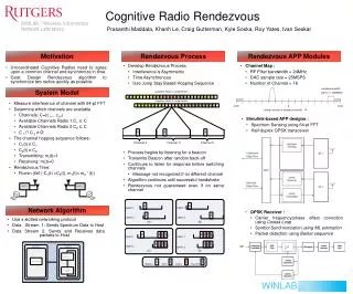
WINLAB Open Cognitive Radio Platform Architecture v1.0. WINLAB – Rutgers University Date : July 27th 2009 Authors : Prasanthi Maddala, prasanthi.m@gmail.com Khanh Le, kle@winlab.rutgers.edu Ivan Seskar, seskar@winlab.rutgers.edu. SDR Tx.

E N D
WINLAB Open Cognitive Radio Platform Architecture v1.0 WINLAB – Rutgers University Date : July 27th 2009 Authors : Prasanthi Maddala, prasanthi.m@gmail.com Khanh Le, kle@winlab.rutgers.edu Ivan Seskar, seskar@winlab.rutgers.edu
SDR Tx • The SDR Tx takes either Control or Data Commands. • These commands are sent as IP packets. OCRP Architecture
SDR Tx Architecture wibo_sen Wibo SPI wibo_sclk System Controller wibo_sdata Rx Ethernet Interface Command Descriptor Generator wibo_u2_sen Command FIFO radio_io5 radio_io6 radio_io7 Dibo SPI Memory Control dibo_sclk dibo_sen dibo_sdata Buffer other outputs Application Block DAC Interface tx_sync tx_data other outputs OCRP Architecture
Frame Format • Control Frame Application Code[4:0] Type [2:0] 00000 - DIBO 000 – Sys Control 00001 - WIBO 001 – App Control 00010 - Tx Application 010 – App Data 00011 – Rx Application Sequence Number : A number given by the user to each frame to keep track of the commands that have been processed and that have been dropped. OCRP Architecture
Data Frame OCRP Architecture
The Rx Ethernet Interface detects an Ethernet frame by looking at the preamble and forwards the Ethernet payload to the next block. It sends out data as 32 bit words and also sends start of frame, end of frame and data valid signals for the next block to sync up. Rx Ethernet Interface OCRP Architecture
Rx Ethernet Interface – FPGA Top IF OCRP Architecture
Rx Ethernet Interface – Command Descriptor Generator IF Rx Ethernet Interface – Register Map IF OCRP Architecture
Command descriptor generator performs the following functions Parses the IP header to see if the destination IP address matches. Generates command descriptors for both the control and data commands and writes them to the command FIFO. Writes the application data to a buffer. Command Descriptor Generator OCRP Architecture
Total Length: 16-bitsThis field indicates the size of the datagram, including the header and the data. OCRP Architecture
Command Descriptor Generator – Memory Control IF OCRP Architecture
Command Descriptor Generator – Command FIFO IF OCRP Architecture
Command Descriptor Generator - Rx Ethernet Interface (As defined in Rx Ethernet Interface – Command Descriptor Generator IF) OCRP Architecture
Command Descriptor Generator – Register Map IF OCRP Architecture
Memory Control • The Memory Control • Keeps track of available buffer space (with the help of write and read ptrs) • Sends an ack or nack on receiving a write request from the command descriptor generator. • Write ptr is updated as and when data is written to the buffer and is wrapped around once it reaches the end. • Read ptr is updated by incrementing the current value by last_app_size whenever the last_app_size_valid is high. When System Control receives app_done for a command it sends out the data size (last_app_size) of the command to the memory control, indicating that the buffer space can be overwritten and the read ptr be updated. OCRP Architecture
Memory Control - Command Descriptor Generator IF (As defined in Command Descriptor Generator – Memory Control IF) OCRP Architecture
Memory Control – Buffer IF OCRP Architecture
Memory Control – System Control IF OCRP Architecture
System Control OCRP Architecture
System Control – Command FIFO Interface OCRP Architecture
System Control - Memory Control IF OCRP Architecture
System Control – Tx Application Interface OCRP Architecture
System Control – Rx Application Interface OCRP Architecture
System Control – WIBO SPI Interface OCRP Architecture
System Control – DIBO SPI Interface OCRP Architecture
WiBo SPI • Used to configure the RF chip(MAX2829), U2,and antenna switches on wibo. • No Data Commands, 1 Control Command • Number of Parameters = 3 - SPI register,U2, Antenna Switches • SPI register (17 : 0) OCRP Architecture
WIBO SPI - System Control IF (As defined in System Control – WIBO SPI Interface) OCRP Architecture
Dibo SPI • Used to configure the ADC/DAC chip (AD9860) on dibo. • No Data Commands, 1 Control Command • Number of Parameters = 1 - SPI register • SPI register (15 : 0) OCRP Architecture
DiBo SPI - System Control IF (As defined in System Control – DIBO SPI Interface) OCRP Architecture
Application Block • System Control IF : • Application Register map values are provided using Parameter setting options e.g. app_param_valid , app_param_data • Data pointer and size information are provided such that App can fetch data/control information from buffer. • Buffer IF : • App fetches buffer data without intervention from System Control. Note that buffer data could be either data or control frame. OCRP Architecture
Application – System Control Interface(as defined in System Control – Application Interface) OCRP Architecture
Application – Buffer Interface OCRP Architecture
Application – DAC Interface OCRP Architecture
DAC Interface • Interleaves the I and Q data from the app block and gives out tx_sync, tx_data to the DAC. • No commands at this point. OCRP Architecture
DAC Interface - Application IF (As defined in Application – DAC Interface) OCRP Architecture
DAC Interface – FPGA Top IF OCRP Architecture