Download
1 / 46
460 likes | 538 Views
Wire Speed Name Lookup A GPU-based Approach. Authors: Yi Wang, Yuan Zu , Ting Zhang, Kunyang Peng , Qunfeng Dong, Bin Liu, Wei Meng , Huichen Dai, Xin Tian , Zhonghu Xu , Hao Wu, Di Yang Publisher: NSDI 2013 Presenter: Chia-Yi Chu Date: 2013/07/03. Outline. Introduction

E N D
Wire Speed Name Lookup A GPU-based Approach Authors: Yi Wang, Yuan Zu, Ting Zhang, KunyangPeng, Qunfeng Dong, Bin Liu, Wei Meng, Huichen Dai, XinTian, ZhonghuXu, Hao Wu, Di Yang Publisher:NSDI 2013 Presenter: Chia-Yi Chu Date: 2013/07/03
Outline • Introduction • Algorithms & Data Structures • The CPU-GPU System: Packet Latency and Stream Pipeline • Memory Access Performance • Implementation • Experimental Evaluation
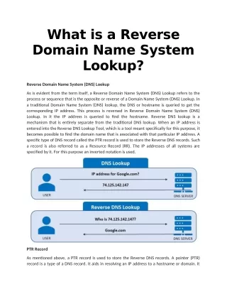
Introduction • Content-Centric Networking (CCN) • use a content name to identify a piece of data instead of using an IP address to locate a device. • every distinct content/entity is referenced by a unique name. • forward packets based on the requested content name(s) carried in each packet header, by looking up a forwarding table consisting of content name prefixes. • CCN name lookup complies with longest prefix matching (LPM) and backbone CCN routers can have large-scale forwarding tables.
Names and Name Tables • Hierarchically structured and composed of explicitly delimited name components • Ex. /com/parc/bulletin/NSDI.html
Challenges • Content names are far more complex than IP addresses. • CCN name tables could be far larger than today’s IP forwarding tables. • Wire speeds have been relentlessly accelerating. • CCN routers have to handle one new type of FIB update.
Algorithms & Data Structures • Name table aggregation • The hierarchical structure of NDN names and the longest prefix matching property • Enable us to aggregate NDN name tables into smaller ones. • One of them is the shortest prefix of the other in the name table • They must map to the same next hop port(s).
FSM • a two-dimensional state transition table. • each state has 256 transitions, and each transition corresponds to a distinct input character. • In 3M table, • 20,440,366 states. • 4 bytes for encoding state ID. • 1,024 bytes are needed for each row. • The entire state transition table takes 19.49 GB memory space. • more than 80% of states have only one single valid transition, plus more than 13% of states (which are accepting states) that have no valid transition at all.
Aligned transition array (ATA) • store valid transitions into what we call an aligned transition array (ATA). • take the sum of current state ID and input character as an index into the transition array • Need to assign each state s a unique state ID, and its input character for verification.
Multi-striding • d characters are processed on each state transition. • component delimiter ‘/’ can only be the last character we read upon each state transition. • Upon state transition, we keep reading in d input characters unless ‘/’ is encountered, where we stop.
Multi-ATA (MATA) • in a d-stride FSM, a state can have transitions at most. • valid transitions stored in the aligned transition array can be as large as . • Defining a maximum ATA length L (L < ) • For a state with state ID x, its valid transition on input number y can be stored in the ((x+y) mod L)th transition array element instead of the (x+y)th element.
suppose state x has another valid transition on input number z. • If y-z is a multiple of L the two valid transitions will be mapped to the same transition array element and hence cause a storage collision. • use a set of prime numbers , such that .
Create a number of small ATAs, each ATA using one of the prime numbers as its maximum length. • Try to store the two valid transitions on y and z into an ATA with prime number L.. • If the two valid transitions do not collide with each other but collide with some valid transition(s) previously stored in that ATA, we shall try another ATA with the same maximum length. • if the two valid transitions collide with each other, we shall move on trying to store state x into an ATA with a different maximum length, until ATAs with all different maximum lengths have been tried.
Name table update • Name deletion • simply conduct a lookup of name P in the name table. • Then backtrack towards the root, remembering all the nodes we have traversed along the path from the root to the leaf node. • deleting the node is equivalent to deleting its stored valid transition in MATA.
Name insertion • Conduct a lookup of name P in the name table, where we traverse the character trie in a top-down manner. • To add an existing node’s new transition on x into MATA, we directly locate the transition array element in which the new transition should be stored. • If that element is vacant, we simply store the new transition into that element • Otherwise, the node needs to be relocated to resolve storage collision.
The CPU-GPU System: Packet Latency and Stream Pipeline • GPU achieves high processing throughput by exploiting massive data-level parallelism • a large batch of names are processed by a large number of GPU threads concurrently • can lead to extended per packet lookup latency
Resolve this latency-throughput dilemma by exploiting the multi-stream mechanism featured in NVIDIA’s Fermi GPU architecture. • Astream is a sequence of operations that execute in issue-order.
Each stream is composed of a number of lookup threads, each thread consisting of three tasks. • DataFetch: copy input names from host CPU to GPU device (via PCIe bus). • Kernel: perform name lookup inside GPU. • WriteBack: write lookup results back from GPU device to host CPU (via PCIe bus).
DataFetch and WriteBacktasks are placed into one queue, executed by the copy engineKerneltasks are organized into another queue, executed by the kernel engine. • Each batch of input names is divided into m subsets; the subset is assigned to the stream for lookup. • By pipelining these concurrent streams, lookup latency can be effectively reduced while keeping high lookup throughput.
The Kerneltask of stream iruns (on the kernel engine) in parallel with the WriteBack task of stream i-1 followed by the DataFetchtask of stream i+1 (both running on the copy engine).
3M name table with 16MB batch size organized into 1∼512 streams, using 2,048 threads. • Reduces lookup latency to 101μs while maintaining lookup throughput (using 128 or more streams).
Throughput • T gets the minimal value at the stationary point , where . • In Figure 5, the CPU-GPU name lookup engine has 16MB, 10μs, 8GB/s (200MSPS *40B/packet). • Engine gets the maximal throughput with N =16 streams.
Latency • lookup latency decreases as the increasing of the stream number N.
Memory Access Performance • To reduce the amount of slow DRAM accesses, by exploiting GPU’s memory access coalescence mechanism. • the off-chip DRAM (e.g. global memory) is partitioned into 128-byte memory blocks. When a piece of data is requested, the entire 128-byte block containing the data is fetched (with one memory access). • When multiple threads simultaneously read data from the same block, their read requests will be coalesced into one single memory access (to that block).
Employ an effective technique for optimizing memory access performance called input interweaving • which stores input names in an interweaved layout. • Every 32 threads (with consecutive thread IDs) are bundled together as a separate warp, running synchronously in a SIMD manner. • when the 32 threads simultaneously read the first piece of data from each of the names they are processing, resulting in 32 separate memory accesses.
Implementation • Platform, environment and tools • CPU: Linux Operating System version 2.6.41.9-1.fc15.x86_64 • GPU: CUDA NVIDIA-Linux operating system version x86_64-285.05.09
Name Tables • 3M name table • 2,763,780 entries • obtain existing domain name information from DMOZ • 10M name table • 10,000,000 entries • use a web crawler program to collect domain names • 3M + 7M
Name Traces • formed by concatenating name prefixes selected from the name table and randomly generated suffixes. • Average workload trace is generated by randomly choosing names from the name table • Heavy workload trace is generated by randomly choosing from the top 10% longest names in the name table
Experimental Evaluation • STT • The baseline method: two-dimensional state transition table • ATA • 4-stride MATA • MATA-NW • Improve MATA with interweaved name
Lookup Performance • CPU-GPU System Performance