Download
1 / 43
440 likes | 579 Views
4.1 introduction 4.2 virtual circuit and datagram networks 4.3 what ’ s inside a router 4.4 IP: Internet Protocol datagram format IPv4 addressing ICMP IPv6. 4.5 routing algorithms link state distance vector hierarchical routing 4.6 routing in the Internet RIP OSPF BGP

E N D
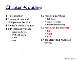
4.1 introduction 4.2 virtual circuit and datagram networks 4.3 what’s inside a router 4.4 IP: Internet Protocol datagram format IPv4 addressing ICMP IPv6 4.5 routing algorithms link state distance vector hierarchical routing 4.6 routing in the Internet RIP OSPF BGP 4.7 broadcast and multicast routing Chapter 4: outline Network Layer
Intra-AS Routing • also known as interior gateway protocols (IGP) • most common intra-AS routing protocols: • RIP: Routing Information Protocol • OSPF: Open Shortest Path First • IGRP: Interior Gateway Routing Protocol (Cisco proprietary) Network Layer
u v w x z y C B D A RIP ( Routing Information Protocol) • included in BSD-UNIX distribution in 1982 • distance vector algorithm • distance metric: # hops (max = 15 hops), each link has cost 1 • DVs exchanged with neighbors every 30 sec via advertisement message • each advertisement: list of up to 25 destination subnetswithin AS from router A to destinationsubnets: subnethops u 1 v 2 w 2 x 3 y 3 z 2 Network Layer
RIP: example z 1 2 y w x 3 B D A C Interface 2 3 3 2 … Destination Network Next Router Num. of hops to dest. w A 2 y B 2 z B 7 x -- 1 …. …. .... Routing/Forwarding table in D Network Layer
A-to-D advertisement dest next hops w - 1 x - 1 z C 4 …. … ... RIP: example z y w x B D A C Interface 2 3 3 2 2 … Destination Network Next Router Num. of hops to dest. w A 2 y B 2 z B A 7 5 x -- 1 …. …. .... Routing/Forwarding table in D Network Layer
RIP: link failure, recovery if no advertisement heard after 180 sec --> neighbor/link declared dead • “routes via the dead neighbor” invalidated • new advertisements sent to neighbors • neighbors in turn send out new advertisements (if tables changed) • link failure info quickly (?) propagates to entire net • poison reverse used to prevent ping-pong loops (infinite distance = 16 hops) Network Layer
routed routed RIP table processing • RIP routing tables managed by application-level process called route-d (daemon) • advertisements sent in UDP packets, periodically repeated transport (UDP) transprt (UDP) network forwarding (IP) table network (IP) forwarding table link link physical physical Network Layer
OSPF (Open Shortest Path First) • “open”: publicly available • uses link state algorithm • LS packet dissemination • topology map at each node • route computation using Dijkstra’s algorithm • advertisements flooded to entire AS • carried in OSPF messages directly over IP (rather than TCP or UDP • IS-IS routing protocol: nearly identical to OSPF Network Layer
OSPF “advanced” features (not in RIP) • security: all OSPF messages authenticated (to prevent malicious intrusion) • multiple same-cost paths allowed (only one path in RIP) • for each link, multiple cost metrics for different TOS • integrated uni- and multicast support: • Multicast OSPF (MOSPF) uses same topology data base as OSPF • hierarchical OSPF in large domains. Network Layer
Hierarchical OSPF boundary router backbone router backbone area border routers area 3 internal routers area 1 area 2 Network Layer
Hierarchical OSPF • two-level hierarchy: local area, backbone. • link-state advertisements only in area • each nodes has detailed area topology • It only know direction (shortest path) to nets in other areas. • area border routers:“summarize” net info. in own area, advertise to other Area Border routers. • backbone routers: run OSPF routing limited to backbone. • boundary routers: connect to other AS’s. Network Layer
Internet inter-AS routing: BGP • BGP (Border Gateway Protocol):the de facto inter-domain routing protocol • “glue that holds the Internet together” • BGP provides each AS a means to: • eBGP: obtain subnet reachability information from neighboring ASs. • iBGP: propagate reachability information to all AS-internal routers. • determine “good” routes to other networks based on reachability information and policy. • allows subnet to advertise its existence to rest of Internet: “I am here” Network Layer
2c 2b 1b 1d 1c 3c BGP message 3a 3b 2a 1a AS1 BGP basics • BGP session:two BGP routers (“peers”) exchange BGP messages: • advertising pathsto different destination network prefixes • exchanged over semi-permanent TCP connections • when AS3 advertises a prefix to AS1: • AS3 promises it will forward datagrams towards that prefix • AS3 can aggregate prefixes in its advertisement AS3 other networks other networks AS2 Network Layer
2c 2b 1b 1d 1c 3a 3b 2a 1a BGP basics: distributing path information • using eBGP session between 3a and 1c, AS3 sends prefix reachability info to AS1. • 1c can then use iBGP do distribute new prefix info to all routers in AS1 • 1b can then re-advertise new reachability info to AS2 over 1b-to-2a eBGP session • when router learns of new prefix, it creates entry for prefix in its forwarding table. eBGP session iBGP session AS3 other networks other networks AS2 AS1 Network Layer
Path attributes and BGP routes • advertised prefix includes BGP attributes • prefix + attributes = “route” • two important attributes: • AS-PATH: contains ASs through which prefix advertisement has passed: e.g., AS 67, AS 17 • NEXT-HOP: indicates specific internal-AS router to next-hop AS • gateway router receiving route advertisement uses import policy to accept/decline • e.g., never route through AS x • policy-basedrouting Network Layer
BGP route selection • router may learn about more than 1 route to destination AS, selects route based on: • local preference value attribute: policy decision • shortest AS-PATH • closest NEXT-HOP router: hot potato routing • additional criteria Network Layer
BGP messages • BGP messages exchanged between peers over TCP connection • BGP messages: • OPEN: opens TCP connection to peer and authenticates sender • UPDATE:advertises new path (or withdraws old) • KEEPALIVE: keeps connection alive in absence of UPDATES; also ACKs OPEN request • NOTIFICATION: reports errors in previous msg; also used to close connection Network Layer
legend: provider B network X W A customer network: C Y BGP routing policy • A,B,C are provider networks • X,W,Y are customer (of provider networks) • X is dual-homed: attached to two networks • X does not want to route from B via X to C • .. so X will not advertise to B a route to C Network Layer
legend: provider B network X W A customer network: C Y BGP routing policy (2) • A advertises path AW to B • B advertises path BAW to X • Should B advertise path BAW to C? • No way! B gets no “revenue” for routing CBAW since neither W nor C are B’s customers • B wants to force C to route to w via A • B wants to route onlyto/from its customers! • BGP에 관련한 중요 사건: http://openweb.or.kr/?p=5620&utm_source=twitterfeed&utm_medium=twitter&utm_campaign=Feed%3A+open-web+%28Open+Web%29&utm_content=Google+International export policy Network Layer
Why different Intra-, Inter-AS routing ? policy: • inter-AS: admin wants control over how its traffic routed, who routes through its net. • intra-AS: single admin, so no policy decisions needed scale: • hierarchical routing saves table size, reduced update traffic performance: • intra-AS: can focus on performance • inter-AS: policy may dominate over performance Network Layer
4.1 introduction 4.2 virtual circuit and datagram networks 4.3 what’s inside a router 4.4 IP: Internet Protocol datagram format IPv4 addressing ICMP IPv6 4.5 routing algorithms link state distance vector hierarchical routing 4.6 routing in the Internet RIP OSPF BGP 4.7 broadcast and multicast routing Chapter 4: outline Network Layer
Unicasting, Broadcasting, Multicasting • 인터넷 전송 방식 • 유니캐스팅(Unicasting): 하나의 송신자가 다른 하나의 수신자로 데이터를 전송하는 방식. 점대점 통신(one-to-one) • 브로드 캐스팅(Broadcasting): 하나의 송신자가 같은 서브네트웍 상의 모든 수신자에게 데이터를 전송하는 방식. • 멀티캐스팅(Multicasting): 동일한 메시지를 하나이상의 수신자에게 동시에 보내는 방식(one-to-many). VOD, 인터넷 화상 회의 등의 응용에서 사용. Network Layer
duplicate creation/transmission duplicate duplicate in-network duplication sourceduplication R4 R2 R1 R4 R3 R2 R1 R3 복습문제 R32와 관련 Broadcast routing • deliver packets from source to all other nodes • source duplication is inefficient: • source duplication: • network is overloaded • how does source determine recipient addresses? Network Layer
Broadcast Routing • N-way Unicast • Broadcast (and Multicast) Network Layer
Broadcast Address • Definition • An IP address that allows information to be sent to all machines on a given subnet rather than a specific machine. • The standard is laid out in RFC 919. • Local Limited Broadcast Address • 255.255.255.255 : • Can be used, during the DHCP (or BOOTP) process, when a host might not know its IP address and subnet mask, and discover DHCP (BOOTP) server • A datagram destined for the limited broadcast address is never forwarded by a router.
Broadcast Address • Net-directed broadcast Address • net Id(netid) + host ID (all one) : • Router must forward a net-directed broadcast by default • but it must also have an option to disable this forwarding. • Class A net-directed broadcast address: netid.255.255.255 • Class B net-directed broadcast address: netid.netid.255.255 • Class C net-directed broadcast address: netid.netid.netid.255 • Subnet-directed Broadcast • net ID (netid) + subnet ID (subnetid) + All host IDs (all one) • Configuration Method • subnet mask - 255.255.192.0 • IP address - 172.16.148.196 • the bit complement of the subnet mask is 0.0.63.255 • 172.16.148.196 || 0.0.63.255 = 172.16.191.255 Network Layer
In-network duplication • flooding: when node receives broadcast packet, sends copy to all neighbors • problems: cycles & broadcast storm • controlled flooding: node only broadcasts pkt if it hasn’t broadcast same packet before • node keeps track of packet ids already broadacsted • or reverse path forwarding (RPF): only forward packet if it arrived on shortest path between node and source • spanning tree: • no redundant packets received by any node Network Layer
(b) broadcast initiated at D (a) broadcast initiated at A G G D D B A B A E E F F c c Spanning tree • first construct a spanning tree • nodes then forward/make copies only along spanning tree Network Layer
G G D D A B E A B E F F c c Spanning tree: creation • center node • each node sends unicast join message to center node • message forwarded until it arrives at a node already belonging to spanning tree 3 4 2 5 1 • stepwise construction of spanning tree (center: E) (b) constructed spanning tree Network Layer
Broadcasting vs. Multicasting • Broadcasting and Multicasting only apply to UDP • The problem with IP broadcasting : • If there are 50 hosts on the cable, but only 20 are participating in the application (Application is designed to use UDP broadcasts), 30 hosts have to process the broadcast, all the way through the UDP layer, before UDP datagram is discarded. • UDP datagram is discarded by these 30 hosts because the destination port number is not in use. • IP broadcasting relies on the underlying router’s setting. Network Layer
Multicasting • Multicast group address • Class D Multicast addresses are identified by the pattern “1110” in the first four bits • 224.0.0.0 – 239.255.255.255 • Host group can locate in multiple networks. • Membership in a host group is dynamic. • Permanent host groups : well-known addresses by IANA • Well-Known Address : 224.0.0.1 ~ 224.0.0.225
Group Management • Multicast Group Management • IGMP (Internet Group Management Protocol) • The IGMP operates between a host and its directly attached router. • It provides the means for a host to inform its attached router that an application running on the hosts wants to join a specific multicast group. Network Layer
Four situation of IGMP operation Network Layer
IGMP in Internet-Wide Net • A host in Internet can join a multicast group Join Join Join Network Layer
legend group member not group member router with a group member router without group member source-based trees Multicast routing: problem statement goal: find a tree (or trees) connecting routers having local multicast group members • tree:not all paths between routers used • shared-tree:same tree used by all group members • source-based:different tree from each sender to rcvrs shared tree Network Layer
Approaches for building mcast trees approaches: • group-shared tree: group uses one tree • center-based trees • source-based tree: one tree per source • shortest path trees • reverse path forwarding Network Layer
Center-based trees (group-shared tree) • single delivery tree shared by all • one router identified as “center” of tree • to join: • edge router sends unicast join-msg addressed to center router • join-msg“processed” by intermediate routers and forwarded towards center • join-msg either hits existing tree branch for this center, or arrives at center • path taken by join-msg becomes new branch of tree for this router Network Layer
Center-based trees: example suppose R6 chosen as center: LEGEND R1 router with attached group member R4 3 router with no attached group member R2 2 1 R5 path order in which join messages generated R3 1 R6 R7 Network Layer
s: source R1 R4 4 3 i 6 1 2 5 R2 R5 R3 R7 R6 Shortest path tree (source-based tree) • mcast forwarding tree: tree of shortest path routes from source to all receivers • Dijkstra’s algorithm LEGEND router with attached group member router with no attached group member link used for forwarding, i indicates order link added by algorithm Network Layer
Reverse path forwarding (source-based tree) if (mcast datagram received on incoming link on shortest path back to center) then flood datagram onto all outgoing links else ignore datagram • rely on router’s knowledge of unicast shortest path from it to sender • each router has simple forwarding behavior: Network Layer
s: source R1 R4 R2 R5 R3 R7 R6 Reverse path forwarding: example LEGEND router with attached group member router with no attached group member datagram will be forwarded datagram will not be forwarded • result is a source-specific reverseSPT Network Layer
Reverse path forwarding: pruning • forwarding tree contains subtrees with no mcast group members • no need to forward datagrams down subtree • “prune” msgs sent upstream by router with no downstream group members s: source LEGEND R1 R4 router with attached group member R2 P router with no attached group member R5 P prune message R3 P links with multicast forwarding R6 R7 Network Layer
Multicast Routing Protocols • IETF Protocols • Distance-Vector Multicast Routing Protocol (DVMRP) – RFC 1075 • Source-based • Reverse Path Forwarding, Pruning • Protocol Independent Multicast (PIM) – RFC 2362 • Dense Mode (RFC 3973, PIM-DM) - Source-based • Sparse Mode (RFC 3569, RFC 4607, PIM-SM) – Both Shard and Source-based Network Layer