
V n-1 V n V n+1
V n-1 V n V n+1. L k n-1 L k n L k n+1. Y n. The Pulse compressor system is based on a high Q 0 storage cavity working on a “whispering gallery” mode TM 10, 1, 1 Q 0 = 197 800 (calculated with HFSS) f 0 = 2.9985 GHz β = Q x / Q 0 = 6. The RF System of the Probe Beam Linac in CTF3.

V n-1 V n V n+1
E N D
Presentation Transcript
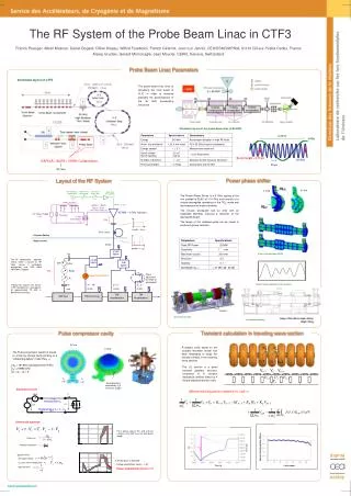
Vn-1 Vn Vn+1 Lkn-1 Lkn Lkn+1 Yn The Pulse compressor system is based on a high Q0 storage cavity working on a “whispering gallery” mode TM10, 1, 1 Q0 = 197 800 (calculated with HFSS) f0 = 2.9985 GHz β = Qx / Q0= 6 The RF System of the Probe Beam Linac in CTF3 Franck Peauger, Alban Mosnier, Daniel Bogard, Gilles Dispau, Wilfrid Farabolini, Patrick Girardot, Jean Luc Jannin, CEA/DSM/DAPNIA, 91191 Gif-sur-Yvette Cedex, France Alexej Grudiev, Gerard Mcmonagle, Jean Mourier, CERN, Geneva, Switzerland Probe Beam Linac Parameters Schematic layout of CTF3 The probe beam linac aims at simulating the main beam of CLIC in order to measure precisely the performances of the 30 GHz accelerating structures Schematic layout of the probe beam linac (CALIFES) 0.33 ns 3 GHz Bunch length< 0.75 ps DAPNIA / IN2P3 / CERN Collaboration 30 GHz 33 ps RF Gun Power phase shifter Layout of the RF System TE10□ H Field E Field Slow Phase Shifter 360 ° RF Generator 2.99855 GHz Fast Phase Shifter 180 ° Solid State Pre-amplifier The Power Phase Shifter is a 3 GHz scaling of the one studied at SLAC at 11.4 GHz and consists of a circular waveguide operating on the TE01 mode and two wrap-around mode converter The circular waveguide has an area with an expanded diameter, inducing a reduction of the waveguide length. The length of this widened guide can be varied to produce a phase variation. PFN (25 cells) 320 kV – 360 A 7.6 µs – 5 Hz 300 W – 3 GHz TE01○ 0.25% ripple during 5.5 µs 45 MW – 3 GHz Klystron + DC Power Supply Thyratron - Pulse Transformer 21.5kV SF6 1:15 45 MW – 5.5 µs BOC Cavity Klystron Gallery Beam Tunnel 90 MW 90 MW – 1.4 µs 4.5 dB Splitter W Electric field simulation (HFSS) The RF components operates mainly under a vacuum of 10-9 mbar. Losses in rectangular waveguides are 0.02 dB/m (WR284 in Copper) 4.5 dB Splitter 3 dB Splitter Circ Ampl SF6 Phase adjustment by length of waveguides Power Phase Shifter F F = - 90° W Taking into account the losses in RF components, a total power of approximately 70 MW is delivered to the linac, F = 0 ° F = 0 ° Electric field superposition for two positions 15 MW 25 MW 22 MW 7 MW TW Acceleration TW Acceleration SW Gun TW bunching bellows 3D mechanical model Surface = 1535 x 400 mm, Heigth = 508 mm Weight = 270 kg 2D mechanical drawing Transient calculation in traveling wave section Pulse compressor cavity E Field Kn-1 Kn A specific code, based on the coupled resonator model has been developed to study the transient effects in the traveling wave sections H Field n-1 n n+1 The LIL section is a quasi constant gradient structure, composed of 9 constant impedance families linked by 4 linearly tapered transition cells Vg Vr Good directivity provided by λg/4 multi-hole coupler Equivalent circuit differential equation relative to cell n Φg(t) ic(t) 1 Forward wave Vg vc(t) vg(t) L C G Backward wave Vr = Vc - Vg Differential equation For a phase step of 57°, and a phase variation until 180° over the total pulse length, Filling time Reflection coefficient Electric Field Amplitude (MV/m) • Approximations : • Sinusoidal voltage A flat top pulse is obtained : - Voltage amplification factor = 1.45 - Power amplification factor = 2.1 - Vg varies slowly compared to Time (s) Cell number - High Q0 factor franck.peauger@cea.fr


![N=n =&gt; width = 1/n US = =1/n 3 [1+4+9+….+n 2 ] US =](https://cdn3.slideserve.com/6895948/slide1-dt.jpg)