Download
1 / 41
430 likes | 760 Views
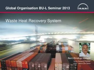
Global Organisation BU-L Seminar 2013. Waste Heat Recovery System. Bent Ørndrup Nielsen Senior Research Engineer LEE4 / Marine Low Speed. MAN Diesel & Turbo Two-stroke engine program. Two-stroke Propulsion. All ME/MC Engine Types available for Waste Heat Recovery

E N D
Global Organisation BU-L Seminar 2013 • Waste Heat Recovery System Bent Ørndrup Nielsen Senior Research Engineer LEE4 / Marine Low Speed
MAN Diesel & TurboTwo-stroke engine program Two-stroke Propulsion All ME/MC Engine Types available for Waste Heat Recovery Higher WHRS output and more advanced systems is economical feasibility the higher engine power.
ProductsEngines & Marine Systems • 2-stroke and 4-stroke engines for marine applications • Output range from 450 kW to 87,220 kW (Low Speed) • Gensets from 450 kW to 11,200 kW • Fuels: diesel, bio-fuels, heavy-fuel oil, gas/dual fuel • Complete propulsion packages • Axial and radial turbochargers for 2-stroke and 4-stroke engines, injection systems • WHRS packages with both exhaust boilers, steam & power turbine generatorunit, PTO/PTI and power management
Renk AG Gearboxes 1 u. 2 MAN Diesel & Turbo Turbocharger The WHRS Principle WHR System - Configuration: MAN Diesel & Turbo Steam Turbine 1,5 – 5,5 MWel Power Turbine 0,5 – 3,5 MWel Dual pressure exhaust gas boiler Generator LP HP LP HP GB2 GB1 Exhaust gas receiver PTI /PTO Main Engine: 27 – 80 MWmech Sum Power Generation (ST/PT): 2 – 9 MWel
High Load OptimizationThe WHRS Principle 12S90ME-C9.2 engine for WHRS SMCR: 69720 kW at 84 rpm ISO ambient reference conditions WHRS: Single pressure (Dual pressure) Total power output 54.3% (55.0%) Electric production of WHRS 5,1% (5,7%) Gain = 10.4% (11.6%) Shaft power Output 49.1% Shaft power Output 49.3% 12S90ME-C9.2 standard engine SMCR: 69720 kW at 84 rpm ISO ambient reference conditions Fuel 100% (167 g/kWh) Fuel 100% (168.7g/kWh) Power-Turbine (PT) in parallel with main engine turbochargers and / or Steam Turbine (ST) utilizing heat in the exhaust gas after the turbochargers Up to approx. 10% MCR power can be obtained with full WHR system (PT+ST) ηstandard ≈ 50%→ηEngine+WHR≈ 55%
ME tuning methods and SFOC • WHR Total curve show the recovered WHRS (ST&PT) energy expressed as SFOC values.
Waste Heat Recovery Systems Options for exhaust Gas Utilisation Power Turbine Stand Alone PTG – Power Turbine Generator Steam Turbine Stand Alone STG – Steam turbine generator Combined Turbines Steam turbine – Power turbine
WHRS – Dual Steam Pressure Stand-alone Power Turbine unit. • Stand-alonePower TurbineUnit • Steam by Compositeboiler with supportfrom GenSet economiser • Possible PTO / PTIadded • ME scavenge airfeed water heatingcan be included • Recovery between 3 to 5%of main engine SMCR powerdepending on size.
Waste Heat Recovery SystemTCS-PTG Programme TCS-PTG based on TCR - Series Type max. Pel TCS-PTG18 1,070 kW TCS-PTG20 1,560 kW TCS-PTG22 2,700 kW TCS-PTG based on TCA - Series Type max. Pel TCS-PTG55 4,020 kW
WHRS – Dual Steam Pressure Steam & Power Turbine unit. • Dual pressuresteam system • Steam & PowerTurbine Units • ME scavenge airfeed water heating • Steam supply fromGenset Economisers • Efficiency between 8 to 11%of main engine SMCR powerdepending on size and servicesteam demand.
WHRS-Marine Waste Heat Recovery System output WHRS data based on: MAN 11S90ME-C9.2 Power: 48560 kW – 79rpm By-pass: 11.2% Recovery rate: 6,8% at 90% SMCR Service steam: 0.5 ton/h (HP) 1.7 ton/h (LP) At ISO condition.
WHRS-Marine Waste Heat Recovery System output WHRS data based on: MAN 11S90ME-C9.2 Power: 48560 kW – 79 rpm By-pass: 11.2% Recovery rate: 8,2% at 90% SMCR (Tropical) Service steam: 0.5 ton/h (HP) 1.7 ton/h (LP) At ISO condition.
WHRS-Marine Engine and WHRS control 3 • If PT control valve closed, EGB valve setting will followMinBP curve. • PT control valve may operatefreely between 0 – MaxBP • If PT control valve setting <MinBP EBP control valve will open, so the area sumwill be MinBP • Increase signal may increaseEGB control valve settingabove MinBP %
The WHR PrincipleInstallation aspects • Size and cost are considerable • Installation complicated • Control aspect • Maintenance Reproduced with permission from OSS
Container ship with WHRS • WHRS installation require largerexhaust pipingsystem – to secureeven exhaust gasdistribution into the exhaust boiler • Collector for exhaustboiler necessary – tocontrol exhaust flowvelocity, velocitydistribution and forcollection of exhaustboiler washing water.
Container ship with WHRS • Exhaust by-passrecommended. • By-pass exhaustvalves in case ofproblems withthe exhaust boiler • PTO / PTI shaftgenerator / motor
WHRS exhaust system and CFD Computational fluid dynamicsThis type of calculation is recommended tosecure even exhaust gas velocity distributioninto the exhaust boiler – guide vanes Pictures given by Lloyd's Register ODS services – www.LR-ODS.com
WHRS exhaust system and back pressure Exhaust system: Exhaust boilers Cone part with guide vanes By-pass pipe Exhaust collector Connections to Turbo Chargers • Back pressure calculationsnecessary • 300 mm w.c. clean condition(Design condition) as maximum required bymain engine. 350 mm w.c.for dirty condition – securing 50 mm w.c. for soot cleaning control. • Higher back pressures can be investigated in caseswhere WHRS and scrubbersystems are combined.
Ship design and Waste Heat Recovery System Early into the ship design Full WHRS need to be taken into the ship design spiral early in order to achievethe best result.
EEDI - Calculation EEDI = ΣP x CF x SFC Capacity x Speed Power Excluded EEDI Power Included EEDI
EEDI - Calculation Πfj (ΣPME*CFME*SFCME) + PAE*CFAE*SFCAE + (Πfj*ΣPPTI –Σfeff*PAEeff)*CFAE*SFCAE - Σfeff*Peff*CFME*SFCME __________________________________________________________________________________ fi * Capacity * Vref * fw PME Main engine 75% of rated main power = 75% *(PMCR(i) – PPTO(i)) • PMCR Main engine Rated main engine power at MCR • PPTO Power Take-off Rated shaft generator at MCR PAE Auxiliary engine 2.5% x PMCR + 250 kW; max 5% x PMCR PPTI Power Take-In 75% of rated shaft motor power PAEeff Aux power reduction Innovative electrical power - including WHR at 75% MCR EEDI =
WHRS Efficiencies & recommendations • Waste Heat Recovery System recovery ratio: • TCS-PTG: 3 – 5 % • MARC_HRS-ST: 4 – 8 % • MARC_HRS-STPT: 7 - 11% • All depending on engine type, size and rating. • Which WHRS solution to select for your ship project – tomb of rule: • Main engine power > 25000 kW Full WHRS (ST&PT) • Main engine power < 25000 kW PTG or STG stand alone • Main engine power < 15000 kW PTG orOrganic Rankine Cycle
WHRS lay-out and ship operation profile Typical for large Container ship Typical for Tankers And Bulk Carriers Ship speed - knots Ship speed - knots • WHRS lay-out according to ship operating profile. • Optimizing around 70 to 80 % ME SMCR at ISO condition • WHRS generator maximum output setting at 90% ME SMCR at Tropicalcondition
WHRS Fuel Oil Prices and Pay back time The higher thefuel price getsthe shorter thepay back timefor the WHRS.The big questionis will fuel pricesstabilise on a higher level orcontinuo to raise? And withwhich rate?
Annual WHRS Output through Engine Load Profile for Container ship
Project Specific WHRS Payback Evaluation – Net Present Value
Two Different Solutions for IMO Tier III NOX Compliance EGR (Exhaust Gas Recirculation) SCR (Selective Catalyst Reduction)
Exhaust gas recirculation and Tier III Recirculation ofexhaust gasmean:Lower O2 forcombustionLeading to lower combustion temperaturesLeading to deduced NOxrelease.
ME tuning methods and SFOC Tier III (EGR) These cases is based on a 10S90ME-C92 engine rated for 49450 kW, Including old tuning and new EGR tuning methods for Tier III. Preliminary data evaluation for EGR tuning.
Exhaust gas recirculation and Tier III and WHRS WHRS steamelements added
WHRS recovery potential.Engine: 10S90ME-C92 SMCR: 49450 kW x 79 rpm
WHRS recovery potential.Engine: 10S90ME-C92 SMCR: 49450 kW x 79 rpm
WHRS and Tier III technologies • The main question for many owners, when ordering new buildings, is which technologies to combine - taking the following into account: • HFO/MDO or LNG or combinations • EGR or SCR as technology for Tier III - IMO Tier III coming into force by 1 January 2016 (Keel laying). • Using HFO both inside and outside ECA and installing scrubber technology for use inside ECA - or using low sulphur fuels /MDO when ever the ship is inside ECA. SOx restrictions from 1 Jan 2015 within ECA. • Owners expected operational profile for the new ships • Fuel prices in the Future
WHRS and Tier III technologies Tier II possibilities
WHRS and Tier III technologies Tier III possibilities
Thank You for Your Attention! • All data provided in this document is non-binding. This data serves informational purposes only and is especially not guaranteed in any way. Depending on the subsequent specific individual projects, the relevant data may be subject to changes and will be assessed and determined individually for each project. This will depend on the particular characteristics of each individual project, especially specific site and operational conditions.