Download
1 / 64
720 likes | 1.35k Views
Chapter 3 Loaders and Linkers. Assembler. Linker. Source Program. Object Code. Executable Code. Loader. 3.1 Basic Loader Functions. In Chapter 2, we discussions Loading: brings the OP into memory for execution

E N D
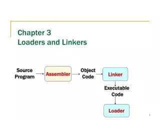
Chapter 3Loaders and Linkers Assembler Linker Source Program Object Code Executable Code Loader
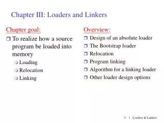
3.1 Basic Loader Functions • In Chapter 2, we discussions • Loading: brings the OP into memory for execution • Relocating: modifies the OP so that it can be loaded at an address different form the location originally specified. • Linking: combines two or more separate OPs (set 2.3.5) • In Chapter 3, we will discussion • A loader brings an object program into memory and starting its execution. • A linker performs the linking operations and a separate loader to handle relocation and loading.
3.1 Basic Loader Functions3.1.1 Design of an Absolute Loader • Absolute loader (for SIC), in Figures 3.1 and 3.2. • Does not perform linking and program relocation. • The contents of memory locations for which there is no Text record are shown as xxxx. • Each byte of assembled code is given using its Hex representation in character form.
3.1.1 Design of an Absolute Loader • Absolute loader, in Figure 3.1 and 3.2. • STL instruction, pair of characters 14, when these are read by loader, they will occupy two bytes of memory. • 14 (Hex 31 34) ----> 00010100 (one byte) • For execution, the operation code must be store in a single byte with hexadecimal value 14. • Each pair of bytes must be packed together into one byte. • Each printed character represents one half-byte.
3.1.2 A Simple Bootstrap Loader • A bootstrap loader, Figure 3.3. • Loads the first program to be run by the computer--- usually an operating system. • The bootstrap itself begins at address 0 in the memory. • It loads the OS or some other program starting at address 80.
3.1.2 A Simple Bootstrap Loader • A bootstrap loader, Figure 3.3. • Each byte of object code to be loaded is represented on device F1 as two Hex digits (by GETC subroutines). • The ASCII code for the character 0 (Hex 30) is converted to the numeric value 0. • The object code from device F1 is always loaded into consecutive bytes of memory, starting at address 80.
3.2 Machine-Dependent Loader Features • Absolute loader has several potential disadvantages. • The actual address at which it will be loaded into memory. • Cannot run several independent programs together, sharing memory between them. • It difficult to use subroutine libraries efficiently. • More complex loader. • Relocation • Linking • Linking loader
3.2.1 Relocation • Relocating loaders, two methods: • Modification record (for SIC/XE) • Relocation bit (for SIC)
3.2.1 Relocation • Modification record, Figure 3.4 and 3.5. • To described each part of the object code that must be changed when the program is relocated. • The extended format instructions on lines 15, 35, and 65 are affected by relocation. (absolute addressing) • In this example, all modifications add the value of the symbol COPY, which represents the starting address. • Not well suited for standard version of SIC, all the instructions except RSUB must be modified when the program is relocated. (absolute addressing)
3.2.1 Relocation • Figure 3.6 needs 31Modification records. • Relocation bit, Figure 3.6 and 3.7. • A relocation bitassociated with each word of object code. • The relocation bits are gathered together into a bit maskfollowing the length indicator in each Text record. • If bit=1, the corresponding word of object code is relocated.
1 1 1 1 1 1 1 1 1 1 1 1 1 0 0 0 0
1 1 1 1 1 1 1 1 1 1 1 0 0 0
1 1 1 1 1 1 1 0 0
3.2.1 Relocation • Relocation bit, Figure 3.6 and 3.7. • In Figure 3.7, T000000^1E^FFC^ (111111111100) specifics that all 10 words of object code are to be modified. • On line 210 begins a new Text record even though there is room for it in the preceding record. • Any value that is to be modified during relocation must coincide with one of these 3-byte segments so that it corresponding to a relocation bit. • Because of the 1-byte data value generated form line 185, this instruction must begin a new Text record in object program.
1111 1111 1100 1110 0000 0000 1110 0000 0000
3.2.2 Program Linking • In Section 2.3.5 showed a program made up of three controls sections. • Assembled together or assembled independently.
3.2.2 Program Linking • Consider the three programs in Fig. 3.8 and 3.9. • Each of which consists of a single control section. • A list of items, LISTA---ENDA, LISTB---ENDB, LISTC---ENDC. • Note that each program contains exactly the same set of references to these external symbols. • Instruction operands (REF1, REF2, REF3). • The values of data words (REF4 through REF8). • Not involved in the relocation and linking are omitted.
ENDA= (S+r1)= PROGA+ENDA=0000+0054 • LISTA=(S+r2)=PROGA+LISTA=0000+0040 • ENDA-LISTA=000014 • ENDA-LISTA+LISTC=000014+(PROGC+LISTC) • 00000A-> FFFFF5+1 -> FFFFF6 • 000040-> FFFFBF+1 -> FFFFC0 • 000010-> FFFFEF+1 -> FFFFF0
REF2 REF4 REF5 REF6 REF7 REF8
REF1 REF3 REF4 REF5 REF6 REF7 REF8
REF1 REF2 REF3 REF4 REF6 REF7 REF8
3.2.2 Program Linking • REF1, LDA LISTA 03201D 03100000 • In the PROGA, REF1 is simply a reference to a label. • In the PROGB and PROGC, REF1 is a reference to an external symbols. • Need use extended format, Modification record. • REF2 and REF3. LDT LISTB+4 772027 77100004 LDX #ENDA-LISTA 050014 05100000
3.2.2 Program Linking • REF4 through REF8, • WORD ENDA-LISTA+LISTC 000014+000000 • Figure 3.10(a) and 3.10(b) • Shows these three programs as they might appear in memory after loading and linking. • PROGA 004000, PROGB 004063, PROGC 0040E2. • REF4 through REF8 in the same value. • For the references that are instruction operands, the calculated values after loading do not always appear to be equal. • Target address, REF1 4040.
4000+0063= 4063+007F=
3.2.3 Algorithm and Data Structure for a Linking Loader • A linking loader usually makes two passes • Pass 1 assigns addresses to all external symbols by creating ESTAB. • Pass 2 performs the actual loading, relocation, and linking by using ESTAB. • The main data structure is ESTAB (hashing table).
3.2.3 Algorithm and Data Structure for a Linking Loader • A linking loader usually makes two passes • ESTAB is used to store the name and address of each external symbol in the set of control sections being loaded. • Two variables PROGADDR and CSADDR. • PROGADDR is the beginning address in memory where the linked program is to be loaded. • CSADDR contains the starting address assigned to the control section currently being scanned by the loader.
3.2.3 Algorithm and Data Structure for a Linking Loader • The linking loader algorithm, Fig 3.11(a) & (b). • In Pass 1, concerned only Header and Defined records. • CSADDR+CSLTH = the next CSADDR. • A load map is generated. • In Pass 2, as each Text record is read, the object code is moved to the specified address (plus the current value of CSADDR). • When a Modification record is encountered, the symbol whose value is to be used for modification is looked up in ESTAB. • This value is then added to or subtracted from the indicated location in memory.
3.2.3 Algorithm and Data Structure for a Linking Loader • The algorithm can be made more efficient. • A reference number, is used in Modification records. • The number 01 to the control section name. • Figure 3.12, the main advantage of this reference-number mechanism is that it avoids multiple searches of ESTAB for the same symbol during the loading of a control section.
3.3 Machine-Independent Loader Features3.3.1 Automatic Library Search • Many linking loaders • Can automatically incorporate routines form a subprogram library into the program being loaded. • A standard system library • The subroutines called by the program begin loaded are automatically fetched from the library, linked with the main program, and loaded.
3.3.1 Automatic Library Search • Automatic library call • At the end of Pass 1, the symbols in ESTAB that remain undefined represent unresolved external references. • The loader searches the library
3.3.2 Loader Options • Many loaders allow the user to specify options that modify the standard processing. • Special command • Separate file • INCLUDE program-name(library-name) • DELETE csect-name • CHANGE name1, name2 INCLUDE READ(UTLIB) INCLUDE WRITE(UTLIB) DELETE RDREC, WRREC CHANGE RDREC, READ CHANGE WRREC, WRITE LIBRARY MYLIB NOCALL STDEV, PLOT, CORREL