Download
1 / 12
120 likes | 275 Views
,. A Contract-Based Methodology for Aircraft Electric Power System Design IEEE TRANSACTIONS ON AEROSPACE AND ELECTRONIC SYSTEMS ,pp.1 - 25 ,ISSN.2169-3536,9 JANUARY 2014.

E N D
, A Contract-Based Methodology for Aircraft Electric Power System Design IEEE TRANSACTIONS ON AEROSPACE AND ELECTRONIC SYSTEMS ,pp.1 - 25 ,ISSN.2169-3536,9 JANUARY 2014. Student:Zhang Jie ID number:0A20F231
Keywords: Aircraft manufacture, Cyberphysical systems, Design automation, Design methodology, Power system stabilty INSPEC: Controlled Indexing CAD, aircraft, aircraft power systems, integer programming, linear programming, power engineering computing, temporal logic INSPEC: Non-Controlled Indexing Boolean variables, aircraft electric power system design, arithmetic constraints, compositional approach, contract-based methodology, control protocol, design space exploration, higher level behavioral model mapping, linear temporal logic, performance model mapping, signal temporal logic, system topology, virtual library components
SUBJECT: I. The Aircraft Electric Power System II. Contract-Based Design of Cyber-Physical Systems III. Platform-Based Flow for Electric Power System Design Using Contracts IV. Electric Power System Topology Design V. Electric Power System Controller Design
INTRODUCTION: The advent of high capability, reliable power electronics together with powerful embedded processors has enabled an increasing amount of “electrification” of vehicles such as cars and aircraft in recent years [1], [2]. Hydraulic, pneumatic and mechanical systems are being replaced by cyber-electrical components that increase the overall system efficiency [3]. However, the increased use of electrically-powered elements poses significant challenges to the aircraft electric power system in terms of the reliability of electrical power generation and distribution while satisfying safety requirements.
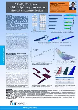
Fig. 1 illustrates a sample architecture for power generation and distribution in a passenger aircraft in the form of a single-line diagram (SLD) [1], a simplified notation for three-phase power systems. Typically, aircraft electric power systems consist of generation, primary distribution and secondary distribution sub-systems. In this paper, we focus on the primary power distribution system, which includes the majority of the supervisory control logic.
The main components of an electric power system are generators, contactors, buses, and loads. Primary generators are connected to the aircraft engine and can operate at high or low voltages. Auxiliary generators are mounted atop an auxiliary power unit (APU). The APU is normally used on ground (when no engines are available) to provide hydraulic and electric power, but can also be used in flight when one of the primary generators fails. With a small abuse of notation, we hereafter refer to auxiliary generators themselves as APUs. Batteries are primarily used at start-up and in case of emergency.
The main AC power sources at the top of Fig. 1include two low-voltage generators, two high-voltage generators, and two APU-mounted auxiliary generators. Each engine connects to a high-voltage AC (HVAC) generator (L1 and R1) and a low-voltage AC (LVAC) generator (L2 and R2). Panels, denoted as dashed square boxes, represent groups of components that are physically separated on the aircraft. The three panels below the generators include the HVAC buses, which can be selectively connected to the HVAC generators, to the auxiliary generators, and to each other via contactors, denoted by double bars.
DESIGN EXAMPLE AND RESULTS: We illustrate our methodology on the proof-of-concept design of the primary power distribution of an electric power system, involving the configuration of contactors to deliver power to high-voltage AC and DC buses and loads. A. Topology Synthesis B. Control Synthesis C. Design Space Exploration for Real-Time Performance
CONCLUSION: We plan to extend our control synthesis algorithms to support richer formal languages (e.g., timed logic, branching logic), continuous-time specifications and continuous dynamics (e.g., transients, network and communication delays). Moreover, we plan to investigate techniques for automatic generation of local contracts for the synthesis of distributed and hierarchical control architectures.
References: 1. I. Moir and A. Seabridge ,Aircraft Systems: Mechanical, Electrical and Avionics Subsystems Integration ,2008, Wiley 2. T. Jomier ,Final MOETtechnical report ,2009 3. K. Sampigethaya and R. Poovendran ,"Aviation cyber-physical systems: Foundations for future aircraft and airtransport" ,Proc. IEEE, vol. 101, pp. 1834-1855, 2013 4. A. Sangiovanni-Vincentelli ,"Quovadis, SLD? Reasoning about the trends and challenges of system level design" ,Proc.IEEE, vol. 95, pp. 467-506, 2007 5. A. Sangiovanni-Vincentelli , W. Damm and R. Passerone ,"Taming Dr. Frankenstein:Contract-based design for cyber-physical systems" ,Proc. Conf. DecisionControl, pp. 1-19, 2011