Download
1 / 45
450 likes | 578 Views
First observation of large Angle Beamstrahlung. Giovanni Bonvicini. What is beamstrahlung. The radiation of the particles of one beam due to the bending force of the EM field of the other beam Many similarities with SR but

E N D
First observation of large Angle Beamstrahlung Giovanni Bonvicini
What is beamstrahlung • The radiation of the particles of one beam due to the bending force of the EM field of the other beam • Many similarities with SR but • Also some substantial differences due to very short “magnet” (L=z/2√2),very strong magnet (3000T at the ILC). Short magnets produce a much broader angular distribution
BBI d.o.f. counting at the ILC • 7 gaussian transverse d.o.f. • 2 beam lengths • At least 4 wake field parameters, and possibly 2 longitudinal • Total 13-15 BBC parameters that may affect the luminosity
Properties of large angle radiation • It corresponds to the near backward direction in electron rest frame (5 degrees at CESR, 2-4 degrees at KEKB/SuperB, 7 degrees at DAPHNE) • Lorentz transformation of EM field produces a 8-fold pattern, unpolarized as whole, but locally up to 100% polarized according to cos2(2), sin2(2) with respect to direction of bending force (Bassetti et al., 1983)
Large angle beamstrahlung power • Total energy for perfect collision by beam 1 is: P0=0.112re3mc2N1N22/(x2z) • Wider angular distribution (compared to quadrupole SR) provides main background separation • CESR regime: exponent is about 4.5 • ILC regime: exponent is very small • KEKB: exponent is small
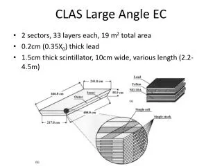
¼ Set-up principal scheme • Transverse view • Optic channel • Mirrors • PBS • Chromatic mirrors • PMT numeration
Detector parameters of interest • Diffraction limit is 0.1 mrad. Sharp cutoff can be assumed • Optics is double collimator. Has triangular acceptance with max width of 1.7mrad • At IP, accepted spot is about 1cm
Set-up general view • East side of CLEO • Mirrors and optic port ~6m apart from I.P. • Optic channel with wide band mirrors
On the top of set-up • Input optics channel • Radiation profile scanner • Optics path extension volume
The ¼ detector • Input channel • Polarizing Beam Splitter • Dichroic filters • PMT’s assembly • Cooling…
Directionality • Scanning is routinely done to reconfirm the centroid of the luminous spot.
Photomultipliers • IR: R2228, has relatively high noise (3-5 kHz). Has filter at 775 nm • VIS: R6095, almost noise-free, has no filter • Previous IR PMTs R-316-02 were discontinued
Typical rates • At HEP conditions, VIS PMTs (West) will have a rate of about 300kHz (0.1Hz channels are used) and IR PMTs about 6kHz. • In the East, 60kHz and 2kHz. • Expected BMST rates are about 500Hz at the nominal theta
Detector systematics detail • Flashlight calibration measures all relative efficiencies to about 0.3%. Absolute efficiencies of VIS PMT >90%, optical channels assumed to be 75+-25%. • Recurrent electronic noise problems on East side (electrons) • Two major data taking periods in July and December 2007 (about 120 good fills each), with dark noise measured every 8 hours.
Data analysis method • The signal sought ought to increase IR light w.r.t. VIS light when a strong beam is opposite, so IR/VIS=k1+k2Ioppo2 • The method also takes into account possible small variations of the bkg through normalization with VIS light • The expected signal in VIS light is of the order of 10-4 of the rate and can be safely ignored • Runs are minimally selected (continuous beams for at least 600 seconds) with chi square and dark noise (cleaning) cuts later to take care of noisy ones
Natural variability of machine provided crucial evidence • In July, relatively high e+ current and relatively low e- current. In December, currents are more balanced, providing a stronger expected BMST signal • In July, e- beam was smaller than e+. In December, the reverse was true. Differing polarizations expected
Main results page • Signal(x) strongly correlated to I+I-2 • Signal strongly polarized according to ratios of vertical sigmas • Total rates consistent with expectations at 10.3 mrad
For those runs where the electron tail did not vary, positive signals are always seen Angle scans show a signal pattern consistent with point-like source. Background pattern is sloping Signal scatter decreases for low noise runs Signal scatter decreases when selecting bands of delta_VIS Signal is negatively correlated with sigma_x, sigma_z as measured by CLEO Numerous cross checks
The first generation Large Angle Beamstrahlung detector was successful, but… This technique is dominated by systematic errors, therefore its only figure of merit is S/B In order to make this technique into a 1% BBI monitor, three conditions must be met: - S/B >>1 (it was 0.02-0.07 at CESR). We can tolerate lower S/B if the tails are proven to be constant during a fill -Much better control over systematics Summary
Conclusions • Large angle Beamstrahlung seen at CESR • Its main features confirmed - in particular, polarization effects • Major sources of systematics found • Interesting for future accelerators in an area of strong need
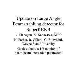
Future Low energy Beamstrahlung detectors Giovanni Bonvicini
The goal: to build an instantaneous Monitor for KEKB and Frascati capable of measuring beam-beam asymmetries to 1%
What to keep • The small azimuthally located viewport(s) • The pointing system • Most of the optics, with changes due to real estate constraints and new observation of multiple wavelengths • PMT-based system
IR PMTs are expensive, noisy, and unneeded in the future. Ideally, use only one type of broadband PMTs with multiple filters PMTs scalers need a lot of bits. Our scalers saturated at 65535 and we sacrificed one viewport on each side to cover all the dynamic range. Multiple scalers on same PMTs (e.g. 0.1 sec and 0.001 sec gate times) recommended Discriminators need to be close to PMTs. 100 ft of coaxial cables are enough to create a lot of noise Telescopes need a major bench calibration before installation assessing angular resolution, PMT spectral response, PMT plateaus, and transmission efficiency of the optics Detector should be robust against 1 mrad misalignments w.r.t. beam axis What needs change but merits no further discussion
Most important change: much stronger beams at KEKB, Frascati (preliminary KEKB numbers courtesy J. Flanagan). Comparison at =5mrad, =500nm
Numerical calculation - Signal spectrum (R=24) versus large theta for two different wavelengths.
First major hardware change: new viewport arrangement • 2 viewports at +-90 degrees provide three crucial advances: • minimal backgrounds according to more advanced MC • insensitive of beam motion, insensitive of beam pipe alignment • At 90 degrees, x-polarization measures U(x), y-polarization measures U(y). Rotation error is minimized
Beam motion at CESR-c. Light curves for two VIS West PMTs during noisy runs
2nd major change: much better event record • CESR record contained BMST data, bunch-by-bunch currents, luminosity monitors, independent measurements of vertical heights, energy, as well as other unused quantities. Beam length and beam horizontal size were computed by measuring size of luminous region using CLEO hadronic events. • Need at least Beam Position Monitors near the IP to monitor beam shifts both in quads and in detector-beam axis angle
If the angle can be considered large and constant… • Assuming (atan(z/)+atan((L-z)/ ) as the field profile, one gets (u=s,c=cos,sin())
Originally, we sought to evaluate a sloping signal against a flat background (sloping and flat vs wavelength) • In fact, at future accelerators the signal will be flat, whereas the background will be sloping. The final choice of wavelength ranges should be done only after the background spectrum has been computed. The number of wavelength bands to be measured depends on the number of d.o.f. of the background. OBSERVATION IN 4 BANDS IS SUGGESTED.
Conclusions • The much stronger beams of KEKB and Frascati should make the detection of beamstrahlung much easier • Large angle beamstrahlung characteristics change at large R • Vast reduction of systematic errors expected from Second Generation device. 1% measurement of beam-beam parameters possible • Technology to be fully mature at the ILC