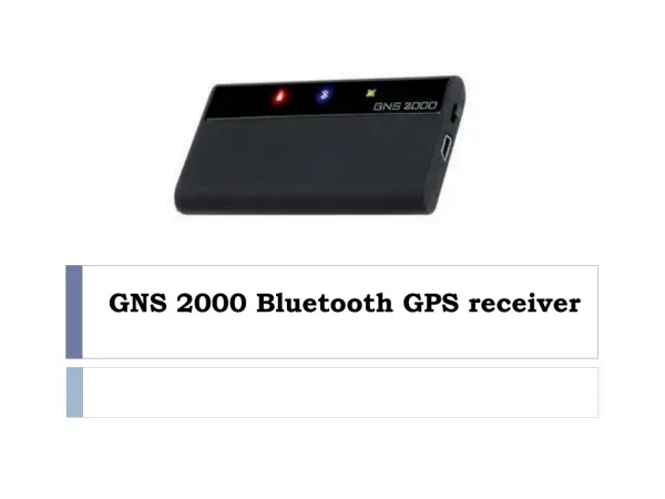
GNS 430 Basic Usage
GNS 430 Basic Usage. VFR GPS Usage. Disclaimer. This briefing is to designed to give an introductory overview so that as you read the GNS 430 Pilot’s Guide and Reference you will have a basic understanding of how this GPS unit can be used for VFR flight. Disclaimer.

GNS 430 Basic Usage
E N D
Presentation Transcript
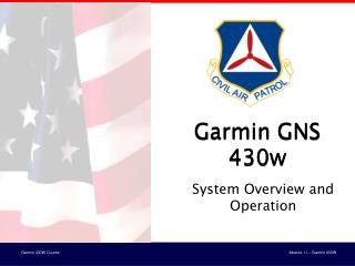
GNS 430 Basic Usage VFR GPS Usage
Disclaimer • This briefing is to designed to give an introductory overview so that as you read the GNS 430 Pilot’s Guide and Reference you will have a basic understanding of how this GPS unit can be used for VFR flight.
Disclaimer • This briefing is not to be used in lieu of the GNS 430 Pilot’s Guide and Reference. • Please read the GNS 430 Pilot’s Guide and Reference for complete instructions. • This can be downloaded for free from http://www.garmin.com/manuals/GNS430_PilotsGuide.pdf
Disclaimer • Garmin provides a GNS 430 PC-based simulator that can run on your home computer. This software can be downloaded for free at http://downloads.garmin.com/GNC400_Trainer_5.01.exe
Disclaimer • It is highly recommended that you download both the reference manual and simulator and practice using the GNS 430 on the ground before using it in the air.
Initial Page • This is the first page you will see when you power on the GNS 430. The unit will then sequence through its self-test routine.
Database Ack. Page • After the unit completes its self-test, you will see the database confirmation page.
Database Ack. Page • The purpose of this page is to notify the user of the effective and expiration dates of the database.
Database Ack. Page • After noting the effective dates, press the ‘ENT’ key to confirm. You will then be advanced to the instrument panel self-test. Press Here
Instrument Panel Self-Test • The instrument panel self-test page allows you to verify that the unit is communicating properly with panel mounted instruments.
Instrument Panel Self-Test • Compare the GNS 430 indications with the depictions on any applicable panel mounted instruments.
Instrument Panel Self-Test • For instance, an external CDI should show halfway to the left with no flag. • LCDI = lateral CDI; LFLG = lateral CDI flag • VCDI = vertical CDI or glide slope; VFLG = vertical CDI or glide slope flag
Instrument Panel Self-Test • Once verified, press the enter key to continue. Press Here
Satellite Status Page • After confirming the database, the satellite page will automatically be displayed. It displays the current satellite status.
Satellite Status Page • The GNS 430 displays the current satellites in ‘view’ and the signal strength of those satellites. Satellite Number and Strength Satellites in ‘view’
Map page after boot… • Once enough satellites have been acquired for navigation, the GNS 430 will automatically cycle to the map page.
Map page after boot… • When you see the map page after the boot sequence the GNS 430 is ready for use.
GNS 430 Controls • We will now cover the basic controls of the GNS 430 for VFR use.
GNS 430 Controls • This briefing is not to be used in lieu of the GNS 430 Pilot’s Guide and Reference.
GNS 430 Controls • Please read the GNS 430 Pilot’s Guide and Reference for complete instructions.
GNS 430 Controls • All of the communication controls are on the left side of the GNS 430.
COM Controls GNS 430 Controls • The COM controls are aligned along the top and the VLOC (VOR-Localizer) controls are aligned below them. VLOCControls
GNS 430 Controls • This is the power/volume/squelch control.
GNS 430 Controls • Turning this knob clockwise will turn the unit on if it does not come on with the avionics master switch.
GNS 430 Controls • Rotating the knob clockwise will increase COM volume. Rotating the knob counter-clockwise will decrease COM volume.
GNS 430 Controls • Pressing this knob in will turn the COM squelch on.
GNS 430 Controls • This is the VLOC volume control. VLOC stands for VOR-Localizer. Press this knob to enable/disable the ident tone.
GNS 430 Controls • This area displays the COM and VLOC frequencies, both active and standby.
GNS 430 Controls • This area displays the COM and VLOC frequencies, both active and standby. COM Active
GNS 430 Controls • This area displays the COM and VLOC frequencies, both active and standby. COM Stby
GNS 430 Controls • This area displays the COM and VLOC frequencies, both active and standby. VLOC Active
GNS 430 Controls • This area displays the COM and VLOC frequencies, both active and standby. VLOC Stby
GNS 430 Controls • The light blue box is the frequency cursor. The cursor can only be located in the COM or VLOC standby frequency box.
GNS 430 Controls • Pressing the small left knob toggles the frequency cursor between COM and VLOC standby frequencies.
GNS 430 Controls • Turn the small left knob to change the kHz value of the standby frequency. (Just remember small knob=small numbers.)
GNS 430 Controls • Turn the large left knob to change the MHz value of the standby frequency. (Big knob=big numbers.)
GNS 430 Controls • This is the VLOC flip-flop button. Press it to swap the VLOC active and standby frequencies.
GNS 430 Controls • This is the COM flip-flop button. Press it to swap the COM active and standby frequencies.
GNS 430 Controls • Holding in the COM flip-flop button for 2 seconds will automatically make the emergency frequency of 121.500 active.
GNS 430 Controls • The CDI key toggles which navigation source, GPS or VLOC, is output to an external CDI or HSI.
GNS 430 Controls • ‘GPS’ or ‘VLOC’ will appear above the CDI key. In this example, GPS is the navigation source.
GNS 430 Controls • In this example, VLOC is the navigation source.
GNS 430 Controls • The OBS key is used to select manual or automatic sequencing of waypoints.
GNS 430 Controls • Pressing the OBS key toggles between manual and automatic sequencing of waypoints.
GNS 430 Controls • Automatic sequencing of waypoints is typically the desired method.
GNS 430 Controls • The absence of any indication above the OBS key means automatic sequencing is the method being used.
GNS 430 Controls • ‘OBS’ will be depicted when manual sequencing has been chosen.
GNS 430 Controls • The MSG key is used to retrieve a message from the GNS 430.
GNS 430 Controls • When the pilot’s attention is needed, “MSG” will flash above the MSG key.
GNS 430 Controls • Pressing the MSG key will replace the current display with the necessary message or messages.