Download

1 / 29
290 likes | 486 Views
Protection and Restoration in Optical Network. Ling Huang Hling@cs.berkeley.edu. Outline. Introduction to Network Survivability Optics in Internet Protection and Restoration in Internet Optical Layer Survivability Protection in Ring Network Protection in Mesh Network

E N D
Protection and Restoration in Optical Network Ling Huang Hling@cs.berkeley.edu
Outline • Introduction to Network Survivability • Optics in Internet • Protection and Restoration in Internet • Optical Layer Survivability • Protection in Ring Network • Protection in Mesh Network • Multi-Layer Resilience • Conclusion.
Network Survivability • A very important aspect of modern networks • The ever-increasing bit rate makes an unrecovered failure a significant loss for network operators. • Cable cuts (especially terrestrial) are very frequent. • No network-operator is willing to accept unprotected networks anymore. • Restoration = function of rerouting failed connections • Survivability = property of a network to be resilient to failure • Requires physical redundancy and restoration protocols.
Data Center SONET SONET SONET SONET DWDM DWDM Metro Long Haul Metro Access Access Optics in the Internet
Layer 3 2 1 0 IP Layer 2/3 0/1 IP ATM SONET MPLS Thin SONET Packet IP/MPLS Packet Optics Optics Inter- working Smart Optical Optical • Multi-physical layers • multi & legacy services • robustness, QOS • Fewer physical layers • IP service dominance • lower cost Optical Network: a Layered vision 2001 1999 2002
Protection and Restoration in Internet • A well defined set of restoration techniques already exists in the upper electronic layers: • ATM/MPLS • IP • TCP • Restoration speeds in different layers: • BGP-4: 15 – 30 minutes • OSPF: 10 seconds to minutes • SONET: 50 milliseconds • Optical Mesh: currently hundred milliseconds to minutes
Why Optical Layer Protection • Restoration in the upper layers is slow and require intensive signaling • On contrary 50-ms range when automatic protection schemes are implement in the optical transport layer. • Purpose of performing restoration in the optical layer: • To decrease the outage time by exploiting fast rerouting of the failed connection. • Main problem in adding protection function in a new layer: • Instability due to duplication of functions. • Need the merging of DWDM and electronic transport layer control and management.
Why Optical Layer Protection? • Advantages. • Speed. • Efficiency. • Limitation • Detection of all faults not possible.(3R). • Protects traffic in units of light paths. • Race conditions when optical and client layer both try to protect against same failure.
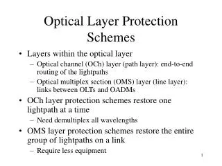
Protection Technique Classification • Restoration techniques can protect the network against: • Link failures • Fiber-cables cuts and line devices failures (amplifers) • Equipment failures • OXCs, OADMs, eclectro-optical interface. • Protection can be implemented • In the optical channel sublayer (path protection) • In the optical multiplex sublayer (line protection) • Different protection techniques are used for • Ring networks • Mesh networks
Protection in Ring Network 1+1 Path Protection Used in access rings for traffic aggregation into central office 1:1 Span and Line Protection Used in metropolitan or long- haul rings 1:1 Line Protection Used for interoffice rings
Protection in Mesh Networks • Network planning and survivability design • Disjoint path idea: service working route and its backup route are topologically diverse. • Lightpaths of a logical topology can withstand physical link failures. Working Path Backup Path
Reactive / Proactive • Reactive • A search is initiated to find a new lightpath which does not use the failed components after the failure happens. • It can not guarantee successful recovery, • Longer restoration time • Proactive • Backup lightpaths are identified and resources are reserved at the time of establishing the primary lightpath itself. • 100 percent restoration • Faster recovery Taxonomy
Normal Operation Path Switching: restoration is handled by the source and the destination. Line Switching: restoration is handled by the nodes adjacent to the failure. Span Protection: if additional fiber is available. Line Switching: restoration is handled by the nodes adjacent to the failure. Line Protection. Path Protection / Line Protection
1+1 Protection • Traffic is sent over two parallel paths, and the destination selects a better one. • In case of failure, the destination switch onto the other path. • Pros: simple for implementation and fast restoration • Cons: waste of bandwidth
1:1 Protection • During normal operation, no traffic or low priority traffic is sent across the backup path. • In case failure both the source and destination switch onto the protection path. • Pros: better network utilization. • Cons: required signaling overhead, slower restoration.
Shared Protection • Backup fibers are used for protection of multiple links • Assume independent failure and handle single failure. • The capacity reserved for protection is greatly reduced. Normal Operation 1:N Protection In Case of Failure
Multiplexing Techniques • Primary Backup Multiplexing • Used in a dynamic traffic scenario, to further improve resource utilization. • Allows a wavelength channel to be shared by a primary and one or more backup paths. • By doing so, the blocking probability of demands decreases at the expense of reduced restoration guarantee. (An increased number of lightpaths can be established) • A lightpath loses its recoverability when a channel on its backup lightpath is used by some other primary lightpath. • It regains its recoverability when the other primary lightpath terminates.
Survivability Design: Joint Optimization Problem • Problem Description • Given a network in terms of nodes (WXCs) and links, and a set of point-to-point demands, find both the primary lightpath and the backup lightpath for each demand so that the total required network capacity is minimized. • Notation • N: the set of nodes; • L: the set of links; • D: the set of demands • Cij: the capacity weight for link (ij) • Wij: the capacity requirement on link (ij) in terms of # of wavelength • Objective • Minimize
Integer Programming Formulation 1) Objective function 2) and 3) the flow conservation constraints for demand d’s primary path and backup path, respectively. 4) Logical relationship: the backup path consumes link capacity iff the primary path is affected by the fault. 5): Restoration route independent of the failure. 6): Link capacity requirement
Multi-Layer Counter-Productive Behavior • Instant response to Level 1 alarms in high layer causes unnecessary routing activity, routing instability, and traffic congestion Link in Traffic Routing table Revision (no link) Routing table Revision (with link) Link Rediscovered ALARM Link recovered through optical protection Link Down 10s ms 10s seconds 10s seconds Source: RHK
Conclusion • Different resilience schemes applicable in optical network have been discussed. • Network planning and topology design for survivability is computationally intractable and faster heuristic solutions are needed. • Multi-layer restoration is a hot point in current optical survivability research. • Joint IP/optical restoration mechanism is the trend in next generation optical network.
Unidirectional Path Switched Ring (UPSR) Signal sent on both working and protected path Best quality signal selected Receiving Traffic Sending Traffic N2 N1 Outside Ring = Working Inside Ring = Protection N3 N4 N1 send data to N2
Unidirectional Path Switched Ring (UPSR) Signal sent on both working and protected path Best quality signal selected Reply Traffic Receiving Traffic N2 N1 Outside Ring = Working Inside Ring = Protection N3 N4 N2 replies back to N1
Bidirectional Line Switched Ring (2-Fiber BLSRs) Sending/Receiving Traffic Sending/Receiving Traffic N2 N1 Both Rings = Working &Protection N3 N4 N1 send data to N2 & N2 replies to N1
Bidirectional Line Switched Ring (4-Fiber BLSRs) Sending/Receiving Traffic Sending/Receiving Traffic N2 N1 OC-48 2 Outside Rings = Working 2 Inside Rings = Protection N3 N4 N1 send data to N2 & N2 replies to N1