Download
1 / 49
490 likes | 626 Views
inst.eecs.berkeley.edu/~cs61c/su06 CS61C : Machine Structures Lecture #14: Combinational Logic, Gates, and State 2006-07-20 Andy Carle. 61C. We’ll investigate lower abstraction layers! (contract between HW & SW). What are “Machine Structures”?. Application (Netscape).

E N D
inst.eecs.berkeley.edu/~cs61c/su06CS61C : Machine StructuresLecture #14: Combinational Logic, Gates, and State2006-07-20Andy Carle
61C We’ll investigate lower abstraction layers!(contract between HW & SW) What are “Machine Structures”? Application (Netscape) Coordination of many levels of abstraction Operating Compiler System (MacOS X) Software Assembler Instruction Set Architecture Hardware Processor Memory I/O system Datapath & Control Digital Design Circuit Design transistors
C compiler assembler ? Below the Program • High-level language program (in C) swap int v[], int k){ int temp; temp = v[k]; v[k] = v[k+1]; v[k+1] = temp; } • Assembly language program (for MIPS) swap: sll $2, $5, 2 add $2, $4,$2 lw $15, 0($2) lw $16, 4($2) sw $16, 0($2) sw $15, 4($2) jr $31 • Machine (object) code (for MIPS) 000000 00000 00101 0001000010000000 000000 00100 00010 0001000000100000 . . .
Digital Design Basics (1/2) • Next 2 weeks: we’ll study how a modern processor is built starting with basic logic elements as building blocks. • Why study logic design? • Understand what processors can do fast and what they can’t do fast (avoid slow things if you want your code to run fast!) • Background for more detailed hardware courses (CS 150, CS 152)
Digital Design Basics (2/2) • ISA is very important abstraction layer • Contract between HW and SW • Can you peek across abstraction? • Can you depend “across abstraction”? • Voltages are analog, quantized to 0/1 • Circuit delays are fact of life • Two types • Stateless Combinational Logic (&,|,~) • State circuits (e.g., registers)
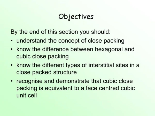
Outline • Truth Tables • Transistors • Logic Gates • Combinational Logic • Boolean Algebra
Transistors (1/3) CMOSFET Transistors: * Physically exist! * Voltages are quantized * Only 2 Types: - P-channel: 0 on gate -> pull up (1) - N-channel: 1 on gate -> pull down (0) * Undriven otherwise. p: n:
Transistors (2/3) CMOSFET Transistors: * have delay and require power * can be combined to perform logical operations and maintain state. - logical operations will be our starting point for digital design - state tomorrow
A B C 0 0 1 0 1 1 1 0 1 1 1 0 Transistors (3/3): CMOS Nand
Logic Gates (1/4) • Transistors are too low level • Good for measuring performance, power. • Bad for logical design / analysis • Gates are collections of transistors wired in a certain way • Can represent and reason about gates with truth tables and Boolean algebra • We will mainly review the concepts of truth tables and Boolean algebra in this class. It is assumed that you’ve seen these before. • Section B.2 in the textbook has a review
Symbol Definition A C B Logic Gates (3/4) AND Gate AND
Boolean Algebra (1/7) • George Boole, 19th Century mathematician • Developed a mathematical system (algebra) involving logic, later known as “Boolean Algebra” • Primitive functions: AND, OR and NOT • The power of BA is there’s a one-to-one correspondence between circuits made up of AND, OR and NOT gates and equations in BA + means OR,• means AND, x means NOT
BA (2/7): e.g., majority circuit y = a • b + a • c + b • c y = ab + ac + bc
BA (6/7): Canonical forms (1/2) Sum-of-products (ORs of ANDs)
Combinational Logic A combinational logic block is one in which the output is a function only of its current input. • Combinational logic cannot have memory. • Everything we’ve seen so far is CL • CL will have delay ( f(transistors) )
Peer Instruction • (a+b)• (a+b) = b • N-input gates can be thought of as cascaded 2-input gates. I.e., (a ∆ bc ∆ d ∆ e) = a ∆ (bc ∆ (d ∆ e))where ∆ is one of AND, OR, XOR, NAND • You can use NOR(s) with clever wiring to simulate AND, OR, & NOT
Administrivia • HW 4 due Friday • Project 2 due Friday the 28th • If you want to get a little bit ahead (in a moderately fun sort of way), start playing with Logisim: • http://ozark.hendrix.edu/~burch/logisim/
Signals and Waveforms • Outputs of CL change over time • With what? Change in inputs • Can graph changes with waveforms …
State • With CL, output is always a function of CURRENT input • With some (variable) propagation delay • Clearly, we need a way to introduce state into computation
Accumulator Example Want: S=0; for i from 0 to n-1 S = S + Xi
First try…Does this work? Feedback! Nope! Reason #1… What is there to control thenext iteration of the ‘for’ loop? Reason #2… How do we say: ‘S=0’? Need a way to store partial sums! …
Circuits with STATE (e.g., register) Need a Logic Block that will: 1. store output (partial sum) for a while, 2. until we tell it to update with a new value.
Register Details…What’s in it anyway? • n instances of a “Flip-Flop”, called that because the output flips and flops betw. 0,1 • D is “data” • Q is “output” • Also called “d-q Flip-Flop”,“d-type Flip-Flop”
What’s the timing of a Flip-flop? (1/2) • Edge-triggered D-type flip-flop • This one is “positive edge-triggered” • “On the rising edge of the clock, the input d is sampled and transferred to the output. At all other times, the input d is ignored.”
What’s the timing of a Flip-flop? (2/2) • Edge-triggered D-type flip-flop • This one is “positive edge-triggered” • “On the rising edge of the clock, the input d is sampled and transferred to the output. At all other times, the input d is ignored.”
Bus a bunch of D FFs together … • Register of size N: • n instances of D Flip-Flop
Yep! Second try…How about this? Roughtiming…
Peer Instruction 2 • Simplify the following Boolean algebra equation: • Q = !(A*B) + !(!A * C) • Use algebra, individual steps, etc. • Don’t just look at it and figure it out, or I’ll have to start using harder examples.
“And In conclusion…” • Use this table and techniques we learned to transform from 1 to another